
User`s manual


AX2200/AX2300 Instruction Manual Chapter 4 Serial Communications
CM2-AX2000-2001 (Rev.4, 4/2014) 4-19
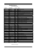
Control Register Definitions
The only writeable registers in this implementation are the Reset Exception
Status, Reset Meter and Reset Totalizer functions, which are implemented as
”coils” which may be written with the Write Single Coil command (function
code 05) to address 7 through 9, respectively, (register #00008 through #00010).
The value sent with this command must be either 0x0000 or 0xff00, or the meter
will respond with an error message; the totalizer will be reset or exception status
cleared only with a value of 0xff00.
Error Responses
If an error is detected in the message received by the unit, the function code
in the response is the received function code with the most significant bit set,
and the data field will contain the exception code byte, as follows:
If the first byte of a message is not equal to the unit’s Modbus address, if the
unit detects a parity error in any character in the received message (with even or
odd parity enabled), or if the message CRC is incorrect, the unit will not
respond.
Command Message Format
The start address is equal to the desired first register number minus one. The
addresses derived from the start address and the number of registers must all be
mapped to valid defined registers, or an invalid data address exception will occur.
Normal Response Message Format
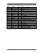
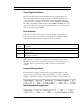
Exception
Code Description
01 Invalid function code — function code not supported by device
02 Invalid data address — address defined by the start address and number of registers
is out of range
03 Invalid data value — number of registers = 0 or >125 or incorrect data with the Write
Single Coil command