
User`s manual


Chapter 4 Serial Communications AX2200/AX2300 Instruction Manual
4-18 CM2-AX2000-2001 (Rev. 4, 4/2014)
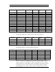
reading a single 16-bit register, then the value will likely be invalid.
The floating point registers with values in display units are scaled to the same
units as are displayed, but are instantaneous values that are not smoothed. If
display smoothing is enabled (non-zero value entered in the Display TC item
in the Display Menu), then the register values will not agree exactly with the
displayed values.
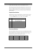
Exception Status Definitions
The Read Exception Status command (function code 07) returns the exception
status byte, which is defined as follows. This byte may be cleared by setting
“coil” register #00003 (function code 5, address 2, data = 0xff00).
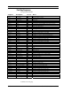
Bit(s) Definition
0-1 Byte order (see Modbus Order on page 2)
0 = 3-2:1-0 1 = 2-3:0-1
2 = 1-0:3-2 3 = 0-1:2-3
2 Not used
3 Not used
4 Not used
5 Not used
6 Not used
7 Configuration changed
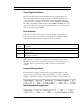
Discrete Input Definitions
The status of the three alarms may be monitored via the Modbus Read Discrete
Input command (function code 02). The value returned indicates the state of the
alarm, and will be 1 only if the alarm is enabled and active. A zero value is
transmitted for alarms that are either disabled or inactive,
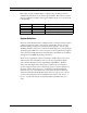
Registers Variable Function Code Address
10001 Alarm #1 state 02 0
10002 Alarm #2 state 02 1
10003 Alarm #3 state 02 2