
User`s manual


Chapter 4 Serial Communications AX2200/AX2300 Instruction Manual
4-16 CM2-AX2000-2001 (Rev. 4, 4/2014)
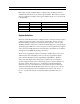
Each range of register numbers maps to a unique range of addresses that are
determined by the function code and the register number. The address is equal to
the least significant four digits of the register number minus one, as shown in the
following table.
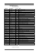
Registers Function Codes Data Type and Address Range
00001-09999 01, 05, 15 Read/write bits 0000-9998
10001-19999 02 Read-only bits 0000-9999
30001-39999 03, 04 Read-only 16-bit registers 0000-9998
40001-49999 03, 06, 16 Read/write 16-bit registers 0000-9998
Register Definitions
The meter serial number and those variables that are commonly monitored (mass,
volume and energy flow rates, total, pressure, temperature, density, viscosity,
Reynolds number, and diagnostic variables such as frequency, velocity, gain,
amplitude and filter setting) are accessible via the Modbus protocol. Long integer
and floating point numbers are accessed as pairs of 16-bit registers in the register
order selected in the Modbus Order menu. Floating point numbers are formatted
as single precision IEEE 754 floating point values.
The flow rate, temperature, pressure, and density variables may be accessed as
either the flow meter internal base units or in the user-programmed display
units, which is determined by the programming Output Menu’s “Modbus
Units” item. The display units strings may be examined by accessing their
associated registers. Each of these units string registers contain 2 characters of
the string, and the strings may be 2 to 12 characters in length with unused
characters set to zero. Note that the byte order affects the order in which the
strings are transmitted. If the Modbus Order menu (see page 2) is set to 0-1:2-3
or 2-3:0-1, then the characters are transmitted in the correct order; if set to 1-
0:3-2 or 3-2:1-0, then each pair of characters will be transmitted in reverse
order.