
User`s manual


Chapter 4 Serial Communications AX2200/AX2300 Instruction Manual
4-14 CM2-AX2000-2001 (Rev. 4, 4/2014)
Menu Items
The following menu items are in the Output Menu and allow selection and
control of the Modbus communication protocol.
Address
When the Modbus protocol is selected, the Modbus address is equal to the
user programmable device address if it is in the range 1…247, in
accordance with the Modbus specification. If the device address is zero or
is greater than 247, then the Modbus address is internally set to 1.
Comm Protocol
The Comm Protocol menu allows selection of “Modbus RTU Even,” “Modbus
RTU Odd,” or “Modbus RTU None2,” or “Modbus RTU None1,” (non-standard
Modbus) with Even, Odd and None referring to the parity selection. When even
or odd parity is selected, the unit is configured for 8 data bits, 1 parity bit and 1
stop bit; with no parity, the number of stop bits is 1 (non-standard) or 2. When
changing the protocol, the change is made as soon as the Enter key is pressed.
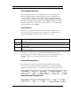
Modbus Units
The Modbus Units menu is to control what units, where applicable, the meter’s
variables will be displayed in. Internal – these are the base units of the meter, °F,
psia, lbm/sec , ft
3
/sec, Btu/sec , lbm/ft
3
Display – variables are displayed in user
selected display unit.
Modbus Order
The byte order within registers and the order in which multiple registers
containing floating point or long integer data are transmitted may be changed
with this menu item. According to the Modbus specification, the most
significant byte of a register is transmitted first, followed by the least significant
byte. The Modbus specification does not prescribe the order in which registers
are transmitted when multiple registers represent values longer than 16 bits.
Using this menu item, the order in which registers representing floating point or
long integer data and/or the byte order within the registers may be reversed for
compatibility with some PLCs and PC software.