
User`s manual

Chapter 2 Installation AX2200/AX2300 Instruction Manual
2-28 CM2-AX2000-2001 (Rev. 4, 4/2014)
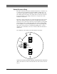
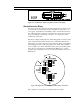
4-20 mA Output Connections
The standard AX2000Series Flow Meter has a single 4-20 mA loop. Two
additional loops are available on the optional communication board. The
4-20 mA loop current is controlled by the meter electronics. The electron-
ics must be wired in series with the sense resistor or current meter. The
current control electronics require 12 volts at the input terminals to oper-
ate correctly.
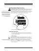
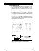
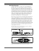
The maximum loop resistance (load) for the current loop output is depend-
ent upon the supply voltage and is given in Figure 2-26. The 4-20 mA loop
is optically isolated from the flow meter electronics.
R
load
is the total resistance in the loop, including the wiring resistance
(R
load
= R
wire
+ R
sense
). To calculate R
max
, the maximum R
load
for the loop,
subtract the minimum terminal voltage from the supply voltage and divide
by the maximum loop current, 20 mA. Thus:
The maximum resistance R
load
= R
max
= (V
supply
– 12V) / 0.020 A
Figure 2-29. Load Resistance Versus Input Voltage
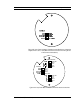
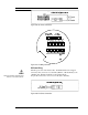
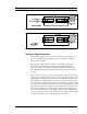
For Hart Communications
signal loop must have a
minimum of 250 ohms load
resistance R
L
R
L
> 250
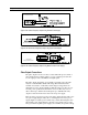
Figure 2-30. Isolated 4–20 mA Output Using External Power Supply