
User`s manual

Chapter 2 Installation AX2200/AX2300 Instruction Manual
2-24 CM2-AX2000-2001 (Rev. 4, 4/2014)
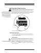
Remote Electronics Wiring
The remote electronics enclosure should be mounted in a convenient, easy
to reach location. For hazardous location installations, make sure to ob-
serve agency requirements for installation. Allow some slack in the inter-
face cable between the junction box and the remote electronics enclosure.
To prevent damage to the wiring connections, do not put stress on the
terminations at any time.
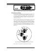
The meter is shipped with temporary strain relief glands at each end of the
cable. Disconnect the cable from the meter’s terminal block inside the
junction box–not at the remote electronics enclosure. Remove both glands
and install appropriate conduit entry glands and conduit. When installa-
tion is complete, re-connect each labeled wire to the corresponding termi-
nal position on the junction box terminal block. Make sure to connect
each wire pair’s shield. Note: incorrect connection will cause the meter to
malfunction.
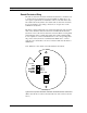
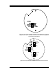
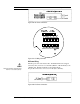
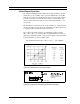
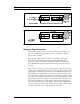
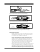
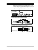
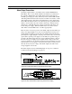
Note: Numeric code in junction box label matches wire labels.
NOT USED
RED 2
SHLD 1&2
BLK 2
FLOW
BLK 1
RED 1
NOT USED
Figure 2-22. Loop Power Volumetric Flowmeter Junction Box Sensor Connections
(Wires enter the flow connector from the left side of the connector shown
above.)