
User`s manual


AX2200/AX2300 Instruction Manual Chapter 2 Installation
CM2-AX2000-2001 (Rev. 4, 4/2014) 2-3
AX2200 In-Line Flow Meter Installation
Install the AX2200 In-Line Flow Meter between two conventional pipe
flanges as shown in Figures 2-3 and 2-4. Table 2-1 provides the recom-
mended minimum stud bolt lengths for wafer-style meter body size and
different flange ratings.
The meter inside diameter is equal to the same size nominal pipe ID in
schedule 80. For example, a 2” meter has an ID of 1.939” (2” schedule
80). Do not install the meter in a pipe with an inside diameter smaller
than the inside diameter of the meter. For schedule 160 and higher
pipe, a special meter is required. Consult the factory before purchasing
the meter.
AX2200 Meters require customer-supplied gaskets. When selecting gas-
ket material make sure that it is compatible with the process fluid and
pressure ratings of the specific installation. Verify that the inside diameter
of the gasket is larger than the inside diameter of the flow meter and adja-
cent piping. If the gasket material extends into the flow stream, it will dis-
turb the flow and cause inaccurate measurements.
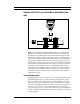
Flange Bolt Specifications
Stud bolt lengths may be calculated using the following equation:
L = Meter face to face length + 2 (mounting flange thickness + flange
raised face) + 2 (gasket thickness) + 4 (mounting nut thickness)
Refer to the mounting flange specification to select the correct stud
bolt diameter.
The required bolt load for sealing the gasket joint is affected by several
application-dependent factors, therefore the required torque for each ap-
plication may be different. Refer to the ASME Pressure Vessel Code
guidelines for bolt tightening standards.
1
2
34
1
2
34
5
6
7
8
1
5
9
3
7
11
2
6
10
4
8
12
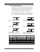
4-bolt 8-bolt 12-bolt
Figure 2-2. Flange Bolt Torquing Sequence