
User`s manual


Chapter 1 Introduction AX2200/AX2300 Instruction Manual
1-8 CM2-AX2200-2001 (Rev. 4, 4/2014)
Flow Meter Configurations
AX2000Series Vortex Mass Flow Meters are available in two
model configurations:
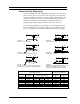
AX2200 In-line flow meter (replaces a section of the pipeline)
AX2300 Insertion flow meter (requires a “cold” tap or a “hot” tap
into an existing pipeline)
Both the in-line and insertion configurations are similar in that they both
use identical electronics and have similar sensor heads. Besides installa-
tion differences, the main difference between an in-line flow meter and
an insertion flow meter is their method of measurement.
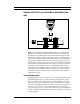
For an in-line vortex flow meter, the shedder bar is located across the en-
tire diameter of the flow body. Thus, the entire pipeline flow is included
in the vortex formation and measurement. The sensing head, which di-
rectly measures velocity, temperature and pressure is located just down-
stream of the shedder bar.
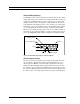
Insertion vortex flow meters have a shedder bar located across the di-
ameter of a short tube. The velocity, temperature and pressure sensor are
located within this tube just downstream of a built-in shedder bar. This
entire assembly is called the insertion sensing head. It fits through any
entry port with a 1.875 inch minimum internal diameter.
The sensing head of an insertion vortex flow meter directly monitors the
velocity at a point in the cross-sectional area of a pipe, duct, or stack (re-
ferred to as “channels”). The velocity at a point in the pipe varies as a func-
tion of the Reynolds number. The insertion vortex flow meter computes the
Reynolds number and then computes the total flow rate in the channel. The
output signal of insertion meters is the total flow rate in the channel. The
accuracy of the total flow rate computation depends on adherence to the
piping installation requirements given in Chapter 2. If adherence to those
guidelines cannot be met, contact the factory for specific installation ad-
vice.
Multivariable Options
The AX2200 or AX2300 models are available with the following op-
tions:
V, volumetric flowmeter; VT, velocity and temperature sensors; VTP,
velocity, temperature, and pressure sensors; VT-EM energy output op-
tions; VTP-EM, energy options with pressure; VT-EP, external pressure
transmitter input.