
User`s manual


AX2200/AX2300 Instruction Manual Chapter 5 Troubleshooting & Repair
CM2-AX2000-2001 (Rev. 4, 4/2014) 5-11
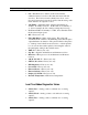
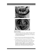
Figure 5-1.Electronics Stack Sensor Connections
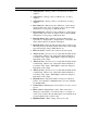
Figure 5-2.Remote Feed Through Board Sensor Connections
Symptom: No Output
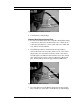
1. For remote mounted electronics, carefully check all the wiring
connections in the remote mount junction box. There are 18
connections that must be correct, verify each color (black and
red), shield, and wire number.
2. Turn on the pressure and temperature display in the Display
Menu and verify that the pressure and temperature are correct.
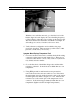
3. Using ESD precautions and hazardous area precautions,
remove the electronics enclosure window cover. Disconnect
the vortex sensor from the electronics stack or remote feed
through board. Refer to Figure 5-1 or 5-2. Measure the
resistance from each outside pin to the meter ground - each
should be open. Measure the resistance from the center pin to
the meter ground – this should be grounded to the meter.
VORTEX
TEMPERATURE
PRESSURE
VORTEX
TEMPERATURE PRESSURE