AXIS 221 Network Camera User’s Manual
About this Document This manual is intended for administrators and users of the AXIS 221 Network Camera, and is applicable for software release 4.15. It includes instructions for using and managing the AXIS 221 on your network. Previous experience of networking will be of use when using this product. Some knowledge of UNIX or Linux-based systems may also be beneficial, for developing shell scripts and applications. Later versions of this document will be posted to the Axis Website, as required.
AXIS 221 Contents Product Features . . . . . . . . . . . . . . . . . . . . . . . . . . . . . . . . . . . . . . . . . . . . . . . . . . . . . . . . . . . . . . . . . 5 Overview . . . . . . . . . . . . . . . . . . . . . . . . . . . . . . . . . . . . . . . . . . . . . . . . . . . . . . . . . . . . 6 Accessing the Camera . . . . . . . . . . . . . . . . . . . . . . . . . . . . . . . . . . . . . . . . . . . . . . . . . . . . . . . . . . . . 8 Access From a Browser . . . . . . . . . . . . . . . . . . . . . . . .
AXIS 221 Troubleshooting . . . . . . . . . . . . . . . . . . . . . . . . . . . . . . . . . . . . . . . . . . . . . . . . . . . . . . . . . . . . . . . . 38 The I/O Units Connectors . . . . . . . . . . . . . . . . . . . . . . . . . . . . . . . . . . . . . . . . . . . . . . . . . . . . . . . . . 43 Power. . . . . . . . . . . . . . . . . . . . . . . . . . . . . . . . . . . . . . . . . . . . . . . . . . . . . . . . . . . . . . 45 The D-Sub Connector . . . . . . . . . . . . . . . . . . . . . . . . . . . . . .
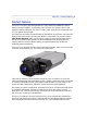
AXIS 221 - Product Features Product Features The AXIS 221 is part of the latest generation of fully featured Axis Network Cameras, based on the AXIS ARTPEC-2 compression chip. The AXIS 221 features a DC-Iris and supports Power over Ethernet. The AXIS 221 has a metal casing and an infrared (IR) filter so it can operate day and night. The video from the camera is made available on the network as a real-time, full frame rate Motion JPEG stream and/or full frame rate MPEG-4 video stream.
AXIS 221 - Product Features The AXIS 221 can be powered from the network cabling and supports Power over Ethernet (PoE) network transformers conforming to IEEE 802.3af.
AXIS 221 - Product Features Network Connector - The camera connects to the network via a standard RJ-45 connector. Supporting NWAY, the camera detects the speed of the local network segment (10BaseT/100BaseTX Ethernet). This socket can also be used to power the AXIS 221 via PoE (Power over Ethernet). The camera can also negotiate the correct power level when using PoE. RS-232 Connector- Single 9-pin D-SUB RS-232 connector, max 115 kbit/s, half-duplex. Serial Number - This number is used during installation.
AXIS 221 - Accessing the Camera Accessing the Camera Follow the instructions in the AXIS 221 Installation Guide to install the camera. The camera can be accessed with most standard operating systems and browsers. The recommended browser is Internet Explorer with Windows, and Mozilla with other operating systems. See also the Technical Specifications, on page 48.
AXIS 221 - Accessing the Camera Setting the Password 1. When accessing a camera for the first time, the ‘Configure Root Password’ dialog will be displayed on the screen. 2. Enter a password and then re-enter it, to confirm the spelling. Click OK. 3. The ‘Enter Network Password’ dialog will appear. Enter the User name: root Note: The default administrator user name root is permanent and cannot be deleted or altered. 4. Enter the password as set in step 2 above, and click OK.
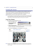
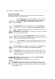
AXIS 221 - Accessing the Camera The Live View Page Depending on whether or not the Live View page has been customized, the buttons described below may or may not be visible. From the Video Format list, select the required video stream format. Note that Multicast has to be enabled if MPEG-4 is selected. This is configured under Setup > System Options > Network > RTP (multicast). The Output buttons control the output directly from the Live View page.
AXIS 221 - Accessing the Camera Click the View Full Screen button to make the video image fill the entire screen area. No other windows will be visible. Press Esc (Escape) on the computer keyboard to exit full screen.
AXIS 221 - Configuration Configuration This section describes how to configure the camera, and is intended for product Administrators, who have unrestricted access to all the Setup tools, and Operators, who have access to the settings for Video & Image, Audio, Live View Config and Event Configuration. The camera is configured under Setup from a standard browser (see Supported Web Browsers, on page 49). Accessing the Setup tools Follow the instructions below to access the Setup Tools from a browser. 1.
AXIS 221 - Configuration Overview of the Setup tools Basic Configuration The links under Basic Configuration are shortcuts providing a convenient way of making the basic settings the first time the unit is configured. Tools Description Instructions General Instructions. Users See System Options > Security > Users below. TCP/IP See System Options > Network > TCP/IP below. Date & Time See System Options > Date & Time below. Video & Image See Video & Image below.
AXIS 221 - Configuration Tools Settings / Options / Description Motion Detection Set up areas in the video image where an alarm is activated whenever movement occurs there. Each motion detection window can be moved, re-sized, or disabled at any time. The behavior for each window is defined by adjusting the Object size, History, and Sensitivity profile sliders. Exclude windows can be used to mask areas where motion should not activate alarms.
AXIS 221 - Configuration Video and Image The following descriptions offer examples of the features available in the AXIS 221. For details of each setting, please refer to the online help available from the setup tools. Click to access the online help. Image Settings Use the Image Appearance settings to change the image as required. The configuration of the video image will affect the camera’s overall performance, depending on how it is used and on the available bandwidth.
AXIS 221 - Configuration Video Stream Define the maximum video stream time per session in seconds, minutes or hours. When the set time has expired, a new stream can be started by refreshing the page in the Web browser. For unlimited video stream time, set this value to 0. This setting is only applicable to Motion JPEG. The frame rate allowed to each viewer can also be limited, to avoid bandwidth problems on the network. Test For a preview of the image before saving, click Test.
AXIS 221 - Configuration Overlay image/privacy mask requirements: Image Formats Image Size • Windows 24-bit BMP (full color) • Windows 4-bit BMP (16 colors) The height and width of the overlay image in pixels must be exactly divisible by 4. • OS/2 4-bit BMP (16 colors) There are a number of limitations when using overlay images and privacy masks, such as the size and positioning of images/masks. Please refer to the online help for more .
AXIS 221 - Configuration MPEG-4 Settings The MPEG-4 standard provides many different coding tools for various applications in different situations. Usually, subsets are defined and used, as it is not reasonable to expect all MPEG-4 clients to support all of these tools. The viewing client must support the subset used for the video stream or the MPEG-4 stream cannot be viewed.
AXIS 221 - Configuration AXIS Media Control The AXIS Media Control (AMC) is installed automatically the first time the camera is accessed from a browser. The AMC control panel can be opened by right-clicking on the video image in the Live View web page. The AMC control panel can be used to configure various video and audio settings, such as push to talk. Please see the readme file included in the tool for more information.
AXIS 221 - Live View Config Live View Config The features on the camera Live View page can be customized to suit your requirements, or you can upload and use your own custom web page. This is done by the administrator from Setup > Live View Config > Layout. Custom Settings To use your own custom web page, click the radio button Use custom settings and click Configure. Upload Own Web Files Your own web files, background pictures, etc.
AXIS 221 - Live View Config 2. Enter the path to the file, e.g. a file located on your computer or click the Browse button. 3. Select the user level for the uploaded file. Setting the user access level means that you have complete control over which pages can be viewed by which users. 4. When the path is shown correctly in the text field, click the Upload button. All uploaded files are shown in the list in the lower section of the page.
AXIS 221 - Live View Config User-defined Links User-defined link Enter a descriptive name and enter the URL in the provided field. Example 1. Check Show Custom Link 1 2. Enter a descriptive name, e.g. My Website 3. Check the radio button for web link. 4. Enter the web link: e.g. http://www.example.com 5. Click Save. This link will then be shown on the Live View page and will open the specified website. User-defined CGI links can be used to issue advanced commands via the Axis HTTP API.
AXIS 221 - Live View Config Output Buttons These buttons can then be used to manually activate the output from the Live View page, e.g. to switch a light on and off. There are 2 options for how the output is activated: • The Pulse button activates the output for a defined period • Active/Inactive displays 2 buttons, one for each action (on/off) Default Video Format in Internet Explorer for Windows. Select default video format from the drop-down list.
AXIS 221 - Live View Config External Video The camera can also display video images from other Axis network cameras and video servers. These are known as External Video sources. Each external video source is available from the drop-down list on the Live View page. Click the Add button to open the External Video Source Setup dialog, which is used to make all the necessary settings. Enter the IP address or host name of the external video source you wish to add.
AXIS 210/211/211A - Event Configuration Event Configuration An event in the camera is when an Event Type is activated and causes certain actions to be performed. The event type is the set of parameters (or conditions) that specifies how and when which actions will be performed. A common event type is when the camera uploads images when an alarm occurs. Many event types use an Event Server, to e.g. upload images to. This section describes how to set up event servers and event types, i.e.
AXIS 210/211/211A - Event Configuration Configuring Event Types An Event Type describes how and when the camera will perform certain actions. Example: If somebody passes in front of the camera, and an event that uses motion detection has been configured to act on this, the camera can e.g. record and save images to an FTP server, and/or send a notification email to a pre-configured email address with a pre-configured message. Images can be sent as email attachments.
AXIS 210/211/211A - Event Configuration Pre-trigger and Post-trigger buffers This function is very useful when checking to see what happened immediately before and/or after a trigger, e.g. 30 seconds before and/or after a door was opened. Check the Upload images checkbox under Event Types > Add Triggered... > Triggered by... to expand the web page with the available options. All uploaded images are JPEG images.
AXIS 210/211/211A - Event Configuration Motion Detection The motion detection feature is used to generate an alarm whenever movement occurs (or stops) in the video image. A total of 10 Include and/or Exclude windows can be configured.
AXIS 210/211/211A - Event Configuration 7. Click Save. To exclude parts of the Include window, click the Configure Excluded Windows button and position the Exclude window as required, within the Include window. Please see the online help for descriptions of each available option.
AXIS 221 - System Options System Options Security User access control is enabled by default. An administrator can set up other users, by giving these user names and passwords. It is also possible to allow anonymous viewer login, which means that anybody may access the Live View page, as described below: Users - the user list displays the authorized users and user groups (levels): Viewer Provides the lowest level of access, which only allows access to the Live View page.
AXIS 221 - System Options HTTPS The AXIS 221 supports encrypted browsing using HTTPS. A self-signed certificate can be used until a Certificate Authority-issued certificate has been obtained. Click the Create self-signed Certificate button to install a self-signed certificate. Although self-signed certificates are free and offer some protection, true security will only be implemented after the installation of a signed certificate issued by a certificate authority.
AXIS 221 - System Options Network - Basic TCP/IP Settings IP Address Configuration The camera’s IP address can be set automatically via DHCP, or a fixed IP address can be set manually. A host name can be used and there are options for setting up notification of changes in the IP address. DHCP is enabled by default. Note: DHCP is a protocol for automatic IP address assignment on a network.
AXIS 221 - System Options Host Name Configuration The camera can be accessed using a host name instead of an IP address. The host name is usually the same as the assigned DNS Name. It is always the first part of a Fully Qualified Domain Name and is always one word, with no period. For example, myserver is the host name in the Fully Qualified Domain Name myserver.mycompany.com.
AXIS 221 - System Options Network - SOCKS SOCKS is a network proxy protocol. The camera can be configured to use a SOCKS server to reach networks on the other side of a firewall/proxy server. This functionality is useful if the camera is located on a local network behind a firewall, but notifications, uploads, alarms, etc., need to be sent to a destination outside the local network (e.g. to the Internet).
AXIS 221 - System Options Ports & Devices I/O Ports The two alarm inputs and one output on the AXIS 221 can be connected to various external devices, e.g. door sensors and alarm bells. The name given to the ports can be changed and state of the I/O ports can be set to Open circuit or Closed circuit. The pinout, interface support and the control and monitoring functions provided by this connector are described in The I/O Units Connectors, on page 43.
AXIS 221 - System Options Backup - To take a backup of all of the parameters, and any user-defined scripts, click the Backup button. If necessary, it is then possible to return to the previous settings if the settings are changed and there is unexpected behavior. Restore - click the Browse button to locate the saved backup file (see above) and then click the Restore button. The settings will be restored to the previous configuration.
AXIS 221 - System Options Resetting to the Factory Default Settings To reset the camera to the original factory default settings, go to the System Options > Maintenance web page (as described in Maintenance, on page 35) or use the Reset button at the rear of the camera (see the illustration on page 6) as described below: Using the Reset Button To reset the camera to the factory default settings using the Reset Button: 1. Disconnect the power adapter, or the network cable if using PoE. 2.
AXIS 221 - Troubleshooting Troubleshooting Checking the Firmware One of your first actions when troubleshooting a problem should be to check the currently installed firmware version. The latest version may contain a correction that fixes your particular problem. The current firmware version in your camera can be seen on the page Setup > Basic Configuration. Upgrading the Firmware Firmware is software that determines the functionality of the camera.
AXIS 221 - Troubleshooting Emergency Recovery Procedure If power or the network connection to the camera is lost during the upgrade, the process will fail and the unit will become unresponsive. A flashing red Status LED indicates a failed upgrade. To recover the unit, follow the steps below. The serial number is found on the label attached to the bottom of the camera. 1.
AXIS 221 - Troubleshooting Symptoms, Possible Causes and Remedial Actions Problems setting the IP address When using ARP/Ping. Try the installation again. The IP address must be set within two minutes after power has been applied to the camera. Ensure the Ping length is set to 408. The camera is located on a different subnet. If the IP address intended for the camera and the IP address of your computer are located on different subnets, you will not be able to set the IP address.
AXIS 221 - Troubleshooting Wrong multicast address. Check with your network administrator what addresses are allowed. Minimum client requirements not fulfilled. Check the client computer specifications, see the Installation Guide. Wrong network interface on client. Check that correct network interface is selected in the AMC control panel applet (network tab). AXIS provided MPEG-4 decoder is not used.
AXIS 221 - Troubleshooting Image loses focus often. Disable the DC-Iris lens in the settings for Video & Image > Advanced. Focus the camera following the instructions on page 9, and then enable the DC-Iris lens. Images only shown in black & white. Check the color level setting. Check the setting for the IR cut filter. Images are shown in color only when this filter is enabled, i.e. when set to yes or auto. Blurred images. Refocus the camera.
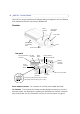
AXIS 221 - The I/O Units Connectors The I/O Units Connectors I/O Terminal Connector Pinout and Interface The 10-pin I/O terminal connector provides the interface to a solid state relay output, two digital photo-coupled inputs, RS-485, GND and auxiliary power. The terminal connector is used in applications for e.g. motion detection, event triggering, time lapse recording, alarm notification via email, image storage to FTP locations, etc.
AXIS 221 - The I/O Units Connectors Pin Function Description 1 Output A 2 Output B The external device output terminals (A and B) there is no distinction between + and -. The terminals use a photocoupler and are electrically isolated from the other internal circuitry. The maximum load should not exceed 100mA and the maximum voltage should be no higher than 50V DC. Note: Connecting AC to the output will damage the unit.
AXIS 221 - The I/O Units Connectors Power Power can be supplied to the camera through the following methods: • the supplied power adaptor, PS-K, 9W. The center pin is positive (+). • PoE (Power over Ethernet) with power classification, Class 2 via the network cable. This will automatically be detected if available via the network. • the power connector block on the rear panel. Power Connector Block The power connector block can handle both AC and DC input power. The DC supply is 7-24V, DC.
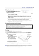
AXIS 221 - The I/O Units Connectors Schematic Diagram - Power Terminal Block and Power Connectors o z Internal 3.3V z Switch Mode Power Supply z z z 3 ~ z z z z AC z o 2 o 1 GND/DC- AC/DC+ = GND +o -o Axis Power Supply PS-K 9V max 9W or according to parts list The D-Sub Connector The AXIS 221 provides one 9-pin D-sub connector, providing the physical interface for an RS-232 port, used for connecting accessory equipment.
AXIS 221 - Replacing the Lens Replacing the Lens If the lens on the AXIS 221 needs to be replaced or if the camera is sold without a lens, a new lens can be fitted quickly and easily. Since the AXIS 221 is designed with a CS-mount, the lens supplied with your product can be replaced with any standard C or CS lens. Note: Although the lens supplied with your product can be directly replaced with any CS-type lens, a C-type lens must be installed with an adaptor for it to work with your AXIS 221.
AXIS 221 - Technical Specifications Technical Specifications Item Specification Image sensor 1/3” Sony Wfine progressive scan RGB CCD Lens Pentax TS3V310ED, F1.0 varifocal 3.0 - 8.0 mm, DC-iris, horizontal viewing angle: 35º-93º, focus range: 0.3 m to infinity. Note that the AXIS 221 is also available without a lens Lens Mount CS Minimum illumination Color: 0.65 lux, F1.
AXIS 221 - Technical Specifications Item Specification Power 7-24 V DC, max 5.5 W (without I/O) 10-24 V AC, max 7.5 VA (without I/O) Power over Ethernet (IEEE 802.af) with power classification according to Class 2 (3.84 to 6.
AXIS 221 - Technical Specifications Item Specification Approvals EMC: EN55024:1998 + A1 + A2 EN61000-6-1:2001 EN61000-6-2:2001 EN55022: 1998 + A1 Class B EN61000-3-2:2000 EN61000-3-3:1995 + A1 FCC Part 15 Subpart B Class B by compliance with EN55022:1998 Class B VCCI:2003 Class B ITE C-tick AS/NZS 3548 Canadian ICES-003 B by compliance with EN55022:1998 Class B Approvals - Safety EN60950 UL CSA MTBF 100,000 hours Dimensions (HxWxD) and weight 49 x 88 x 186 mm (115/16” x 315/32” x 75/16”) 550 g (
Glossary of Terms HTTP - Hypertext Transfer Protocol. The set of rules for exchanging files (text, images, sound, video, and other files) on the World Wide Web. ActiveX - A control (or set of rules) used by a browser. ActiveX controls are often downloaded and installed automatically as required. HTTPS - Hypertext Transfer Protocol over Secure Socket Layer. A web protocol that provides encryption for page requests from users and for the pages returned by the web server.
Pre/post alarm image - The images from immediately before and after an alarm. Privacy mask - An image or specified area used to block out certain parts of the video image. Protocol - A special set of rules governing how two entities will communicate. Protocols are found at many levels of communication, and there are hardware protocols and software protocols. Router - A device that determines the next network point to which a packet should be forwarded on its way to its final destination.
AXIS 221 - Index 53 Index A Action 25 Action Buttons 10, 22 Active/Inactive 10, 23 Administrator 12 Administrators 30 Alarm 28, 43 AMC 8 AMC Viewer Toolbar 10 Auxiliary Power 43 AXIS Media Control 19 B Backup 36 Basic Configuration 13 Buffer Size 27 Buffers 27 C CGI links 22 Configuration 12 Connectors 46 D Date & Time 31 Default Viewer 23 DNS Configuration 32 DNS Server 32 Domain Name 32 D-Sub Connector 46 E Emergency Recovery 39 Event Servers 25 Event Types 26 Events 25 External Video 24 Externa
AXIS 221 - Index Ports & Devices 35 Post-trigger Buffer 27 Power Connector 6 Pre-trigger Buffer 27 Pulse 10, 23 R Recovery 39 Referrals 30 Reset Button 7 Restart 35 Restore 35, 36 RS-232 serial interface 46 S Scheduled Event 25, 27 Security 30 Sequence Mode 10, 24 Server Time 31 Services 32 Setup Tools 13 Snapshot button 10 Support 36 System Options 30 System Options Overview 14 T TCP Server 25 TCP/IP Settings 32 Time Mode 31 Triggered Event 25 Troubleshooting 38 U Upgrade Server 35 Uploading we