
User`s manual


User’s Manual
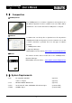
1-4-5. Pin Figure
, the user should only use them after being familiarized with the usage
The following pictures show the usage of the connector pins used in the USB2Dynamixel. To make them
suitable for the intended purpose
of each pin.
Pin Figure of 4P/3P Cable Connector
Pin No. Signal Pin Figure Pin No. Signal Pin Figure
1GND 1GND
2 NOT Connected 2 NOT Connected
3 DATA + (RS-485) 3 DATA (TTL)
4 DATA - (RS-485)
4 Pin Cable 3 Pin Cable
321
4321
Pin Figure of Serial Connector
Pin No. Signal Pin Figure
1 Data (TTL)
2 RXD (RS-232)
3 TXD (RS-232)
4 D+ (RS-485)
5GND
6 D- (RS-485)
7 Short with No. 8
8 Short with No. 7
9 USB power (5V)
8