
Manual

Re-mount the tubes between the gas valve and the burners. (Smear gearing of
the connection, where the collar on the tube and the tube are mounted to the
gas valve, with gas paste against gas leakage.)
Change the labels of the appliance according to the gas conversion type.
Connect the appliance to appropriate type of gas according to the gas
conversion.
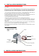
Check all connections for gas leakage. (Tests have to be carried out using
leakage spray or foam. Never check gas leakage with an open fire source like
match, lighter etc.)
After the gas leakage test carry out combustion test for the appliance.
If the heat of the appliance is not sufficient set the gas adjustment injector (by-
pass) on the gas valve appropriately using a screwdriver. (Since the by-pass
injector is opened into the gas flow path, do never remove the by-pass injector
during operation. Since the settings of the appliance are done by default as to
requested gas pressure; if gas conversion will not be carried out, these settings
should never be changed by the user. Re-mount the back panel if no problem
exists.
If you follow these instructions you can use your appliance safely with the gas
type converted.
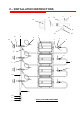
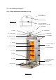
2.3.4 – Gas System Diagram
1 – Burner
2 – Burner connection
3 – Burner injector
4 - Splint
5 – Ring
6 – Burner collar
7 – Gas tube
8 – Gas valve
9 – Thermo-element
10 – Gas ramp
11 – Gas pressure control connection
12 – Natural gas connection collar
13 – Propane connection collar
14 – Gas valve button
15 – Gas valve nut
16 – Gas valve by-pass injector
17 – Gas valve collar
18 – Gas valve clamp
19 – Clamp screw
20 - Gas tube counter nut
2 – INSTALLATION INSTRUCTONS