
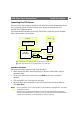
Instruction manual

The RS-232 Interface AXIS 2400+/2401+ Admin Manual
48
Appendix F - The RS-232 Interface
The AXIS 2400+/2401+ has two 9-pin D-sub connectors, providing the physical interface for
two RS-232 ports, used for connecting:
• accessory equipment; such as stand-alone Pan/Tilt devices for remote positioning of con-
nected video cameras
• any standard modem for use in remote applications
• the AXIS 2191Audio Module, as described on page 28.
As a complement to the information provided in Pan Tilt Settings, on page 23, this
appendix describes how to install a standalone Pan/Tilt device to the AXIS 2400+/2401+
Video Server.
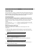
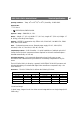
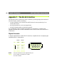
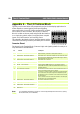
Physical Connector
A diagram representative of both RS-232 connectors, complete with an accompanying pin
assignment table, is shown below.
Notes: The pinout is different for each supported serial port.
Pin 4 on COM1 is connected to Pin 7 (RTS).
NC = Not connected
Pin
COM1
Function
COM2
Function
1 NC CD
2 - RXD - RXD
3 - TXD - TXD
4 DTR DTR
5 GND GND
6 DSR DSR
7 RTS RTS
8 NC CTS
9 NC RI
54321
6789