INSTALLATION GUIDE ENGLISH AXIS Q8721-E Dual PTZ Network Camera
Legal Considerations Equipment Modifications Trademark Acknowledgments Liability Video and audio surveillance can be prohibited by laws that vary from country to country. Check the laws in your local region before using this product for surveillance purposes. This product includes two (1) H.264 decoder licenses. To purchase further licenses, contact your reseller.
Safeguards Please read through this Installation Guide carefully before installing the product. Keep the Installation Guide for further reference. • Risk of pinching. Do not touch the product while it is moving. • This Axis product shall be used in compliance with local laws and regulations. • Do not install the camera near heat sources since fluctuating temperatures may affect thermal image quality. • The Axis product should be installed by a trained professional.
AXIS Q8721-E Installation Guide Page 5 AXIS Q8721-E Installation Guide This Installation Guide provides instructions for installing an AXIS Q8721-E Dual PTZ Network Camera on your network. For all other aspects of using the product, please see the User Manuals, available at www.axis.
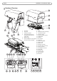
Page 6 AXIS Q8721-E Installation Guide Hardware Overview 1 2 3 4 5 9 8 10 11 7 1 2 3 4 6 5 6 12 13 14 15 n/a n/a 13 16 17 18 19 20 n/a Sunshield Top cover Protective window Illuminator bracket screw with washer (4x) and lock washer (4x) Bottom cover Dual PTZ Network camera (pan/ tilt control unit and motor) 14 15 19 7 8 9 10 11 12 13 14 15 16 17 18 19 20 21 22 23 24 25 26 n/a Base Illuminator (sold separately) Illuminator bracket Network camera Thermal network camera CVBS button Audio in SD
AXIS Q8721-E Installation Guide Page 7 Install the Hardware For information on the cameras’ connectors, LED behaviors etc., see the respective User Manuals. Install the Power Supply (sold separately) The mains supply shall be disconnected during installation. The day/night sensor is attached to the power supply (sold separately). If using the day/night sensor, place the power supply so that the sensor can track the changes in daylight. 1.
Page 8 AXIS Q8721-E Installation Guide Install the Bracket (sold separately) 1. Prepare a wall, parapet or pole for installation of the selected bracket (sold separately). See www.axis.com for information on available mounting accessories. 2. Route the network, power and, if applicable, illuminator cables through the bracket. Leave approximately 50 cm (11.8”) of cable for connecting the base.
AXIS Q8721-E Installation Guide Page 9 4. Assemble the screws, washers and screw seals. 5. Put the seal in its position.
Page 10 AXIS Q8721-E Installation Guide Attach the Base to the Bracket 1. Remove the desiccant bag, which is placed in the base. 2. Make sure the seal is in position. 3. Route the network, power and, if applicable, illuminator cables through their respective cable glands in the base. The cable glands are suitable for cables with a diameter of 5 mm - 10 mm. For cables with a diameter 3 mm 7 mm, use the supplied spare gaskets. 4. Screw the cable gland caps on firmly.
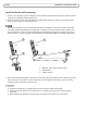
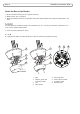
AXIS Q8721-E Installation Guide Page 11 5. Attach the base to the bracket and tighten the screws (torque 4 Nm). Apply Loctite 243 threadlocker on the screws. 1 1 2 2 3 4 3 5 1 2 3 4 5 Base Alignment indicator Screw (4x) Column bracket Wall bracket ENGLISH The base can be attached to the bracket in four different positions.
Page 12 AXIS Q8721-E Installation Guide 6. If applicable, connect the illuminator cable to the connector (ALARMS and 1) on the base. 7. Using a RJ45 crimp tool, strip and crimp the network cable according to the manufacturer’s instructions. 8. Connect the network cable to the network connector on the base. The power supply specified with the product shall be used. Using any other power supply will void the warranty and could leave the unit at a risk. 9.
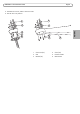
AXIS Q8721-E Installation Guide Page 13 Attach the Dual PTZ Network Camera to the Base 1. Make sure the seal is in position. 2. Remove the sunshield, which is placed on but not attached to, from the top cover. 3. Attach the Pan/Tilt control unit, motor and camera assembly to the base and tighten the screws (torque 4 Nm). Use the alignment indicators to align the units. Incorrect alignment could cause damage to components.
Page 14 AXIS Q8721-E Installation Guide Install the Counterweights 1. Unscrew the bottom cover screws and remove the top cover, see illustration on page 15. 2. Attach the counterweights to the bottom cover using the supplied screws and washers (torque 4 Nm). Apply Loctite 243 threadlocker on the screws. 3. Secure the counterweights using the supplied grub screws (torque 4 Nm).
AXIS Q8721-E Installation Guide Page 15 4. Attach the top cover to the bottom cover. Make sure to tighten diagonally opposite bottom cover screws a few turns at a time until all are tight (torque 4 Nm). This will help ensure that the bottom cover gasket is compressed evenly. 5. Attach the sunshield to the top cover. 6. Loosen the counterweight locking screws and adjust the position of the weights to the desired position. The positions of the weights must be identical.
Page 16 AXIS Q8721-E Installation Guide 8. Switch on the mains supply. The pan/tilt control unit will start turning and the cameras will turn on approximately 30 seconds later. In cold temperatures, there might be a delay due to the de-icing process, see Day/Night Sensor, on page 17. Risk of pinching. Do not touch the product while it is moving.
AXIS Q8721-E Installation Guide Page 17 Configuration For information about how to assign an IP address and gain access to the product, see Access the Video Stream, on page 18 and the Installation and Management Software CD. PTZ The PTZ functionality is controlled through the network camera. The PTZ controls will be available from the Live View page in the network camera’s web pages after enabling the PTZ functionality. See the User Manual, available at www.axis.
Page 18 AXIS Q8721-E Installation Guide Access the Video Stream Use the tools provided on the Installation and Management Software CD to assign an IP address, set the password and access the video stream. This information is also available from the support pages on www.axis.com/techsup Focus Adjustment - AXIS Q1921 If required, follow these instructions to focus the thermal network camera: 1. Unscrew the stop screw on the lens, using a slotted screwdriver 1.8 mm. Stop screw 2.
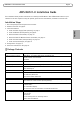
AXIS Q8721-E Installation Guide Page 19 Resetting to the Factory Default Settings This will reset all parameters, including the IP address, to the Factory Default settings: 1. 2. 3. 4. Troubleshooting This table applies to the pan/tilt and illumination units only. For troubleshooting of the network cameras, see the respective User Manuals. Disconnect the mains supply before performing any kind of maintenance procedure. The product is not running Make sure all the connections are correct.
Page 20 AXIS Q8721-E Installation Guide Technical Specifications For technical specifications of the network cameras, see the respective User Manuals. Function/group Item Specifications Camera Model AXIS Q8721-E, includes AXIS Q1755 and AXIS Q1921 General Pan/Tilt Pan: 360° endless, 0.1° – 20°/s Tilt: +45° to -20°, 0.1° – 20°/s Protocol Pelco D Preset accuracy 0.
Installation Guide AXIS Q8721-E © Axis Communications AB, 2013 Ver.1.10 Printed: January 2013 Part No.