INSTALLATION GUIDE ENGLISH AXIS Q6042-E PTZ Dome Network Camera FRANÇAIS AXIS Q60 Series AXIS Q6044-E PTZ Dome Network Camera DEUTSCH AXIS Q6045-E PTZ Dome Network Camera ITALIANO ESPANÕL ò ¨ ¾
Legal Considerations Support Video surveillance can be regulated by laws that vary from country to country. Check the laws in your local region before using this product for surveillance purposes. This product includes one (1) H.264 decoder license. To purchase further licenses, contact your reseller. Should you require any technical assistance, please contact your Axis reseller.
This product fulfills the requirements for immunity according to EN 61000-6-1 residential, commercial and light-industrial environments. This product fulfills the requirements for immunity according to EN 61000-6-2 industrial environments. This product fulfills the requirements for immunity according to EN 55024 office and commercial environments Australia/New Zealand This digital equipment fulfills the requirements for RF emission according to the Class A limit of AS/NZS CISPR 22.
AXIS Q60 Series Safety Information Hazard Levels DANGER Indicates a hazardous situation which, if not avoided, will result in death or serious injury. WARNING Indicates a hazardous situation which, if not avoided, could result in death or serious injury. CAUTION Indicates a hazardous situation which, if not avoided, could result in minor or moderate injury. NOTICE Indicates a situation which, if not avoided, could result in damage to property.
AXIS Q60 Series Safety Instructions WARNING • The Axis product shall be installed by a trained professional. NOTICE • The Axis product shall be used in compliance with local laws and regulations. • Store the Axis product in a dry and ventilated environment. • Avoid exposing the Axis product to shocks or heavy pressure. • Do not install the product on unstable brackets, surfaces or walls. • Use only applicable tools when installing the Axis product. Excessive force could cause damage to the product.
AXIS Q60 Series WARNING • Risk of explosion if the battery is incorrectly replaced. • Replace only with an identical battery or a battery which is recommended by Axis. Dome Cover NOTICE • Be careful not to scratch, damage or leave fingerprints on the dome cover because this could decrease image quality. If possible, keep the protective plastic on the dome cover until the installation is complete. • Do not clean a dome cover that looks clean to the eye and never polish the surface.
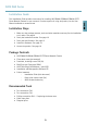
AXIS Q60 Series Installation Guide Installation Steps 1. Make sure the package contents, tools and other materials necessary for the installation are in order. See page 9. 2. Study the hardware overview. See page 10. 3. Study the specifications. See page 13. 4. Install the hardware. See page 14. 5. Access the product. See page 18.
AXIS Q60 Series Optional Accessories • AXIS T91A Mounting Accessories • Smoked dome cover • RJ45 IP66-rated Cable with Premounted Connector (CAT6) 5 m • AXIS T8310 Video Surveillance Control Board • AXIS T90A Illuminators • Installation Display • Midspan For information about available accessories, see www.axis.
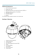
AXIS Q60 Series Dome Cover 1 3 4 5 6 1 2 3 4 5 6 Dome bracket screw PH2 (4x) Dome bracket Rubber gasket Dome ring Dome ring screw T30 (4x) Dome cover Sunshield 1 1 2 Screw holes Holes for unit holders 11 2 ENGLISH 2
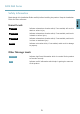
AXIS Q60 Series LED Indicators LED Color Indication Status Unlit Connection and normal operation Amber Steady during startup. Flashes during firmware upgrade. Amber/red Flashes amber/red if network connection is unavailable or lost. Red Flashes red for firmware upgrade failure. Green Shows steady green for 10 seconds for normal operation after restart. Midspan LED Indicators LED Color Indication Port Unlit No camera connected. Green Steady when camera connected, normal operation.
AXIS Q60 Series SD card slot - A standard or high-capacity SD card (not included) can be used for local recording with removable storage. To prevent corruption of recordings, the SD card should be unmounted before removal. To unmount, go to Setup > System Options > Storage > SD Card and click Unmount. Control button - The control button is used for: • • Resetting the product to factory default settings. See page 18. Connecting to an AXIS Video Hosting System service or AXIS Internet Dynamic DNS Service.
AXIS Q60 Series Install the Hardware NOTICE • The AXIS product shall be connected using a shielded network cable (STP). All cables connecting the product to the midspan shall be shielded (STP) and intended for their specific use. Make sure that the midspan is properly grounded. For information about regulatory requirements, see Regulatory Information, on page 2. • Mount the product with the dome cover facing downward.
AXIS Q60 Series Install an SD Card It is optional to install a standard or high capacity SD card (not included), which can be used for local recording with removable storage. 1. Loosen the dome ring screws and remove the dome cover. 2. Insert an SD card (not included) into the SD card slot. 4. To attach the dome cover to the top cover, align the bulge on the dome cover with the heater on the camera unit and tighten the screws (torque 1.5 Nm).
AXIS Q60 Series 1 4 2 3 1 2 3 4 Screw T30 (3x) Slot for unit holder (3x) Safety wire Wall bracket (mounting example) 5. Loosen the grounding screw and remove the washer and cable shoe.
AXIS Q60 Series 2 3 4 5 1 2 3 4 5 Network connector – RJ45 Push-pull Connector (IP66) Network connector and network connector shield Ground screw T20 Washer Cable shoe 6. Attach the grounding wire to the cable shoe using cable shoe pliers. 7. Put the cable shoe and washer back in their original positions and tighten the screw (torque 0.5 Nm). Make sure the cable shoe is in contact with the grounding surface. 8. Connect the network cable to the camera.
AXIS Q60 Series Install the Midspan The supplied midspan enables Axis network video products with high power consumption to receive data and power over the same network cable. 1. Connect the midspan (data in) to the network switch using a network cable. 2. Connect the midspan (data and power out) to the camera using the network cable that has been connected to the camera. 3. Connect the midspan to a grounded (earthed) mains power outlet (100–240 V AC) using the supplied power cable.
AXIS Q60 Series Note The installation and management software tools are available on the CD supplied with the product and from the support pages on www.axis.com/techsup 1. Press and hold the control button and the power button for about 15–30 seconds until the status LED indicator flashes amber. See Hardware Overview, on page 10. 2. Release the control button but continue to hold down the power button until the status LED indicator turns green. 3. Release the power button and assemble the product. 4.
AXIS Q60 Series Informations sur la sécurité Lisez attentivement ce guide d'installation avant d'installer l'appareil. Conservez le Guide d'installation pour référence ultérieure. Niveaux de risques Indique une situation dangereuse qui, si elle n'est pas évitée, entraînera le décès ou des blessures graves. AVERTISSEMENT Indique une situation dangereuse qui, si elle n'est pas évitée, pourrait entraîner le décès ou des blessures graves.
AXIS Q60 Series Consignes de sécurité AVERTISSEMENT • Le produit Axis doit être installé par un professionnel formé. AVIS • Le produit Axis doit être utilisé conformément aux lois et réglementations locales en vigueur. • Conserver ce produit Axis dans un environnement sec et ventilé. • Ne pas exposer ce produit Axis aux chocs ou aux fortes pressions. • Ne pas installer ce produit sur des supports, surfaces ou murs instables.
AXIS Q60 Series AVERTISSEMENT • Risque d'explosion si la batterie est remplacée de façon incorrecte. • Remplacez-la uniquement par une batterie identique ou une batterie recommandée par Axis. • Mettez au rébut les piles usagées conformément aux réglementations locales ou aux instructions du fabricant de la batterie. Couvercle de dôme • Veillez à ne pas rayer, endommager ou laisser d'empreintes sur le couvercle du dôme car cela pourrait altérer la qualité d'image.
AXIS Q60 Series Guide d'installation Ce Guide d'installation fournit des instructions pour l'installation de la caméra dôme réseau Q6042-E/Q6044-E/Q6045-E PTZ sur votre réseau. Pour toute autre information relative à l'utilisation du produit, reportez-vous au manuel de l'utilisateur disponible sur le site www.axis.
AXIS Q60 Series Accessoires en option • Accessoires de montage AXIS T91A • Couvercle de dôme fumé • Câble RJ45 de 5 m compatible norme IP66 avec connecteur préinstallé (catégorie 6) • Tableau de contrôle de vidéosurveillance AXIS T8310 • Illuminateurs AXIS T90A • Moniteur d’installation • Injecteur Pour plus d’informations sur les accessoires disponibles, consultez le site www.axis.
AXIS Q60 Series Couvercle de dôme 1 2 3 5 6 1 2 3 4 5 6 Vis du support pour caméra dôme PH2 (x4) Support pour caméra dôme Joint en caoutchouc Garniture pour caméra dôme Vis de la garniture pour caméra dôme T30 (x4) Couvercle de dôme Pare-soleil 1 1 2 Trous de vis Trous pour supports de caméra 27 2 FRANÇAIS 4
AXIS Q60 Series Voyants Voyant Couleur Indication État Éteint Branchement et fonctionnement normal Orange Fixe pendant le démarrage. Clignote pendant la mise à niveau du microprogramme. Orange / rouge Clignote en orange / rouge en cas d'indisponibilité ou de perte de la connexion réseau. Rouge Clignote en rouge en cas d'échec de la mise à niveau du microprogramme. Vert Vert fixe pendant 10 secondes pour indiquer un fonctionnement normal après le redémarrage.
AXIS Q60 Series AVIS • Le produit doit être connecté à l'aide d'un câble réseau blindé (STP). Tous les câbles reliant le produit à l'injecteur doivent être blindés (STP) et destinés à leur usage spécifique. Assurez-vous que l'injecteur est convenablement mis à la terre. Pour plus d’informations sur les exigences réglementaires, consultez . Fente pour carte SD - Une carte SD standard ou à haute capacité (non fournie) peut être utilisée pour l’enregistrement local sur stockage amovible.
AXIS Q60 Series Produit Classification Température Humidité AXIS Q6042-E IEC 60721-4-3 Classe 3K3, 3M3 IEC 60529 IP66 De -40 °C à 50 °C (-40 °F à 122 °F) Humidité relative de 10 à 100 % (condensation) AXIS Q6044-E Humidité relative de 10 à 100 % (condensation) Humidité relative de 10 à 100 % (condensation) AXIS Q6045-E Consommation électrique AVIS Utilisez une source d'alimentation limitée (LPS) conforme aux exigences de Très basse tension de sécurité (TBTS) dont la puissance de sortie nominale e
AXIS Q60 Series • • • • Le produit est fourni avec un couvercle de dôme non fumé (prémonté). Un couvercle de dôme fumé est disponible en tant qu'accessoire. Pour remplacer le couvercle du dôme, reportez-vous à la page 31. Une carte SD standard ou à haute capacité (non fournie) peut être utilisée pour sauvegarder des enregistrements dans l'appareil. Pour installer une carte SD, reportez-vous à la page 31.
AXIS Q60 Series Support de fixation (vendu séparément) AVIS • Le produit doit être mis à la terre à l'aide d'un câble de mise à la terre. Assurez-vous que les deux extrémités du câble de mise à la terre sont en contact avec les surfaces de mise à la terre correspondantes. • Pour être conforme à la norme IP66 de la caméra et maintenir la protection IP66, il est nécessaire d'utiliser le connecteur push-pull RJ45 fourni (conforme à la norme IP66).
AXIS Q60 Series 5. Desserrez les vis de mise à la terre et retirez la rondelle et la cosse de câble. 2 3 4 5 1 2 3 4 5 Connecteur réseau - Connecteur push-pull RJ45 (conforme à la norme IP66) Connecteur réseau et blindage du connecteur réseau Vis de mise à la terre T20 Rondelle Cosse de câble 6. Fixez le câble de mise à la terre à la cosse de câble à l'aide de pinces à sertir pour cosses de câble. 7. Remettez la cosse de câble et la rondelle en place et serrez la vis (couple 0,5 Nm).
AXIS Q60 Series Installation de l'injecteur L'injecteur fourni permet aux produits de vidéo sur IP d'Axis à forte consommation d’énergie de recevoir les données et l'alimentation électrique sur le même câble réseau. 1. Branchez l'injecteur (données) au commutateur réseau à l'aide d'un câble réseau. 2. Connectez l'injecteur (sortie des données et de l’alimentation) sur la caméra via le câble réseau qui a été branché à la caméra. 3. Connectez l'injecteur à une sortie du secteur mise à la terre (100–240 V c.a.
AXIS Q60 Series Pour réinitialiser l'appareil aux paramètres d'usine par défaut : Informations complémentaires Vous trouverez le Manuel d'utilisation sur www.axis.com. Rendez-vous sur le site www.axis.com/techsup pour vérifier si des mises à jour de microprogramme sont disponibles pour votre produit réseau. Pour connaître la version du microprogramme actuellement installée, accédez à Setup > About (Configuration > À propos de). Visitez le Centre d'apprentissage AXIS sur www.axis.
AXIS Q60 Series Sicherheitsinformation Lesen Sie das Installationshandbuch sorgfältig durch bevor sie das Produkt installieren. Bewahren Sie das Installationshandbuch für zukünftige Zwecke auf. Gefährdungsstufen GEFAHR Weist auf eine gefährliche Situation hin, die, falls nicht verhindert, zu Tod oder schweren Verletzungen führen kann. WARNUNG Weist auf eine gefährliche Situation hin, welche, falls nicht verhindert, zu Tod oder schweren Verletzungen führen kann.
AXIS Q60 Series Sicherheitsanweisungen WARNUNG • Das Axis Produkt muss von fachmännischem Personal installiert werden. HINWEIS • Die Anwendung des Axis Produkts muss unter Beachtung der örtlich geltenden rechtlichen Bestimmungen erfolgen. • Lagern Sie das Axis Produkt in einer trockenen und belüfteten Umgebung. • Achten Sie darauf, dass das Axis Produkt weder Stößen noch starkem Druck ausgesetzt ist. • Installieren Sie das Produkt nicht an instabilen Halterungen, Oberflächen oder Wänden.
AXIS Q60 Series WARNUNG • Explosionsgefahr bei fehlerhaftem Batteriewechsel. • Ersetzen Sie nur durch eine identische Batterie oder einer von Axis empfohlenen Batterie. • Verbrauchte Batterien sind gemäß örtlicher Bestimmungen oder Herstelleranweisungen zu entsorgen. Kuppelabdeckung HINWEIS • Achten Sie darauf die Kuppelabdeckung weder zu zerkratzen, zu beschädigen oder darauf Fingerabdrücke zu hinterlassen, da dies die Bildqualität beeinträchtigen kann.
AXIS Q60 Series Installationsanleitung Die Installationsanleitung enthält Anweisungen zur Installation der AXIS Q6042-E/Q6044E/Q6045-E PTZ-Dome-Netzwerkkamera in Ihrem Netzwerk. Weitere Aspekte zur Nutzung dieses Produktes finden Sie im Benutzerhandbuch unter www.axis.com Installationsschritte 1. Stellen Sie sicher, dass die Packungsinhalte, Werkzeuge und andere notwendige Materialien für die Installation in Ordnung sind. Siehe Seite 41. 2. Machen Sie sich mit der Hardware-Übersicht vertraut.
AXIS Q60 Series Optionales Zubehör • AXIS T91A Montagezubehör • Getönte Kuppelabdeckung • RJ45-Kabel mit Schutzart IP66 und vorbelegtem Stecker (CAT6), Länge 5 m • AXIS T8310 Steuerungseinheit zur Videoüberwachung • AXIS T90A Leuchten • Installationsmonitor • Midspan Unter www.axis.com finden Sie Informationen über verfügbares Zubehör.
AXIS Q60 Series Kuppelabdeckung 1 2 3 4 5 1 2 3 4 5 6 Kuppelhalterungsschraube PH2 (4x) Kuppelhalterung Gummidichtung Kuppelring Kuppelringschraube T30 (4x) Kuppelabdeckung Sonnenblende 1 1 2 Schraubenbohrungen Bohrungen für Gerätehalter 43 2 DEUTSCH 6
AXIS Q60 Series LED-Anzeigen LED Farbe Bedeutung Status Leuchtet nicht Anschluss und Normalbetrieb Gelb Leuchtet beim Start. Blinkt bei der FirmwareAktualisierung. Gelb/rot Blinkt gelb/rot, wenn die Netzwerkverbindung nicht verfügbar ist oder unterbrochen wurde. Rot Blinkt rot bei einem Fehler während der Firmware-Aktualisierung. Grün Leuchtet bei Normalbetrieb nach dem Start 10 Sekunden lang grün.
AXIS Q60 Series HINWEIS • Das Produkt sollte mit einem abgeschirmten Netzwerkkabel (STP) angeschlossen werden. Alle Kabel, die das Produkt mit dem Midspan verbinden, sollten abgeschirmt (STP) und nur für die bestimmte Anwendung eingesetzt werden. Stellen Sie sicher, dass der Midspan vorschriftsmäßig geerdet ist. Informationen zu gesetzlichen Bestimmungen finden Sie unter .
AXIS Q60 Series Produkt Klassifikation Temperatur Luftfeuchtigkeit AXIS Q6042-E IEC 60721-4-3 Klasse 3K3, 3M3 IEC 60529 IP66 -40 °C bis 50 °C (-40 °F bis 122 °F) 10–100% rF (kondensierend) AXIS Q6044-E AXIS Q6045-E 10–100% rF (kondensierend) 10–100% rF (kondensierend) Stromverbrauch HINWEIS Verwenden Sie eine mit den Anforderungen für Schutzkleinspannung (SELV) kompatible Stromquelle mit begrenzter Leistung (LPS), entweder mit einer Nennausgangsleistung von ≤100 W oder einem dauerhaft auf ≤5 A beg
AXIS Q60 Series • • • • Das Produkt wird mit einer vormontierten durchsichtigen Kuppelabdeckung geliefert. Eine getönte Kuppelabdeckung ist als optionales Zubehör erhältlich. Weitere Informationen zum Austausch der Kuppelabdeckung finden Sie unter Seite 47. Eine Standard SD-Karte oder eine SD-Karte mit hoher Kapazität (nicht enthalten) kann verwendet werden, um Aufnahmen direkt auf dem Produkt zu speichern. Weitere Informationen zur Installation einer SD-Speicherkarte finden Sie unter Seite 47.
AXIS Q60 Series 1. Lösen Sie die Kuppelringschrauben und entfernen sie die Kuppelabdeckung. 2. Schieben Sie die SD-Karte (nicht enthalten) in den SD-Karteneinschub. 4. Bringen Sie die Kuppelabdeckung an der oberen Abdeckung an, indem Sie die Ausbuchtung der Kuppelabdeckung am Heizelement der Kameraeinheit ausrichten und die Schrauben festziehen (Drehmoment 1,5 Nm). HINWEIS Um einer Beschädigung der Aufnahmen vorzubeugen, sollte die SD-Karte ausgerastet werden, bevor diese ausgeworfen wird.
AXIS Q60 Series 1 4 2 3 DEUTSCH 1 2 3 4 Schraube T30 (3x) Steckplatz für Steuerungshalter (3x) Sicherheitsdraht Wandhalterung (Montagebeispiel) 5. Lösen Sie die Masseschraube und entfernen Sie die Unterlegscheibe und den Kabelschuh.
AXIS Q60 Series 1 2 3 4 5 1 2 3 4 5 Netzwerkanschluss – RJ45-Stecker zum Stecken/Ziehen (IP66) Netzwerkstecker und Abschirmung des Netzwerksteckers Masseschraube T20 Unterlegscheibe Kabelschuh 6. Befestigen Sie das Erdungskabel mithilfe der Kabelschuh-Zange am Kabelschuh. 7. Bringen Sie den Kabelschuh und die Unterlegscheibe zurück in die Originalposition und ziehen Sie die Schrauben fest (Drehmoment 0,5 Nm). Sorgen Sie dafür, dass der Kabelschuh Kontakt zur Erdungsfläche hat. 8.
AXIS Q60 Series Midspan installieren Der bereitgestellte Midspan ermöglicht Axis Netzwerkvideoprodukten mit hohem Stromverbrauch, Daten und Strom über das selbe Netzwerkkabel zu empfangen. 1. Verbinden Sie den Midspan (Dateneingang) mit dem Netzwerkschalter, indem Sie das Netzwerkkabel verwenden. 2. Verbinden Sie den Midspan (Daten- und Stromausgang) mit der Kamera durch das Netzwerkkabel, welches mit der Kamera verbunden wurde. 3.
AXIS Q60 Series Zurücksetzen auf werkseitige Standardeinstellungen Wichtig Das Zurücksetzen auf die werkseitigen Standardeinstellungen sollte mit Vorsicht verwendet werden. Beim Zurücksetzen auf die werkseitigen Standardeinstellungen werden alle Einstellungen einschließlich der IP-Adresse auf die werkseitigen Standardeinstellungen zurückgesetzt. Beachten Die Software-Tools für Installation und Verwaltung sind auf der mit dem Produkt ausgelieferten CD-ROM und über die Supportseiten unter www.axis.
AXIS Q60 Series Garantieinformationen Informationen zur Garantie der Axis Produkte und hierzu verbundene Informationen, finden Sie unter www.axis.
AXIS Q60 Series Informazioni di Sicurezza Leggere questa Guida d'Installazione prima di installare il prodotto. Conservare la Guida d'Installazione per usi futuri. Livelli di pericolo PERICOLO Indica una situazione pericolosa che, se non evitata, provoca morte o lesioni gravi. AVVERTENZA Indica una situazione pericolosa che, se non evitata, può provocare la morte o lesioni gravi. ATTENZIONE Indica una situazione pericolosa che, se non evitata, può provocare lesioni medie o minori.
AXIS Q60 Series Istruzioni di sicurezza AVVERTENZA • Il prodotto Axis deve essere installato da un professionista qualificato. AVVISO • Il prodotto Axis deve essere utilizzato in conformità alle leggi e alle disposizioni locali. • Conservare il prodotto Axis in un ambiente asciutto e ventilato. • Evitare di esporre il prodotto Axis a urti o pressioni eccessive. • Non installare il prodotto su supporti, superfici o pareti instabili. • Utilizzare solo strumenti applicabili quando si installa il prodotto Axis.
AXIS Q60 Series AVVERTENZA • Rischio di esplosione se la batteria viene sostituita in modo errato. • Sostituire solo con una batteria identica o una batteria consigliata da Axis. • Smaltire le batterie usate in base alle normative locali o alle istruzioni del produttore della batteria. Coperchio della cupola AVVISO • Fare attenzione a non graffiare, danneggiare o lasciare impronte sul coperchio della cupola, perché potrebbe diminuire la qualità dell'immagine.
AXIS Q60 Series Guida all'installazione Questa guida all'installazione fornisce istruzioni per l'installazione della telecamera di rete a cupola AXIS Q6042-E/Q6044-E/Q6045-E PTZ sulla rete. Per ulteriori informazioni sull’utilizzo del prodotto, consultare la Guida per l'utente disponibile all'indirizzo www.axis.com Procedure di installazione 1. Assicurarsi che il contenuto della confezione, gli strumenti e altri materiali necessari per l'installazione siano in ordine. Consultare pagina 59. 2.
AXIS Q60 Series • Copertura a cupola sfumata • Cavo RJ45 di classe IP66 con connettore premontato (CAT6) da 5 m • Scheda di controllo videosorveglianza AXIS T8310 • Illuminatori AXIS T90A • Display d'installazione • Midspan Visitare il sito web www.axis.com per informazioni sugli accessori disponibili.
AXIS Q60 Series Coperchio della cupola 1 2 3 4 5 6 Vite staffa cupola PH2 (4) Staffa cupola Guarnizione in gomma Anello cupola Viti anello cupola T30 (4x) Coperchio della cupola ITALIANO 1 2 3 4 5 6 Parasole 1 1 2 Fori per le viti Fori per i supporti dell’unità 61 2
AXIS Q60 Series Indicatori LED LED Colore Indicazione LED di stato Spento Connessione e operazione normale Giallo Costante durante l'avvio. Lampeggia durante l'aggiornamento del firmware. Giallo/rosso Lampeggia in giallo/rosso se il Collegamento di rete non è disponibile o è stato perso. Rosso Lampeggia in rosso se l'aggiornamento del firmware non è andato a buon fine. Verde Una luce verde fissa per 10 secondi indica il normale funzionamento dopo il riavvio.
AXIS Q60 Series AVVISO • Il prodotto deve essere collegato con un cavo di rete schermato (STP). Tutti i cavi che collegano il prodotto al midspan devono essere schermati (STP) e destinati al loro uso specifico. Assicurarsi che il midspan sia propriamente a terra. Per maggiori informazioni sui requisiti normativi, consultare . • È necessario utilizzare il Connettore push-pull RJ45 (IP66) in dotazione per mantenere inalterate le caratteristiche di tenuta e protezione di classe IP66 della telecamera.
AXIS Q60 Series Prodotto Classificazione Temperatura Umidità AXIS Q6042-E IEC 60721-4-3 Classe 3K3, 3M3 IEC 60529 IP66 Da -40 °C a 50 °C (da -40 °F a 122 °F) 10–100% RH (umidità relativa con condensa) AXIS Q6044-E 10–100% RH (umidità relativa con condensa) AXIS Q6045-E 10–100% RH (umidità relativa con condensa) Consumo energetico AVVISO Utilizzare una sorgente di alimentazione limitata (LPS) compatibile con una bassissima tensione di sicurezza (SELV) con una potenza di uscita nominale limitata a
AXIS Q60 Series • • • • Insieme al prodotto, viene fornito un coperchio trasparente per la cupola (premontato). È disponibile un coperchio per la cupola fumé come accessorio. Per sostituire il coperchio della cupola, consultare pagina 65. Una scheda SD standard o ad alta capacità (non inclusa) può essere utilizzata per memorizzare le registrazioni localmente nel prodotto. Per installare una scheda SD, consultare pagina 65.
AXIS Q60 Series 2. Inserire una scheda SD (non inclusa) nello slot per schede SD. 4. Per fissare il coperchio della cupola sulla copertura superiore, allineare la protuberanza sul coperchio della cupola con il riscaldatore della telecamera e serrare le viti (serraggio 1,5 Nm). AVVISO Per prevenire il danneggiamento delle registrazioni, la scheda SD deve essere smontata prima dell'espulsione.
AXIS Q60 Series 1 4 2 3 1 2 3 4 Vite T30 (3) Slot per supporti unità (3x) Cavo di sicurezza Staffa a muro (esempio montaggio) 67 ITALIANO 5. Allentare le viti della messa a terra, quindi rimuovere la rondella e il capocorda.
AXIS Q60 Series 1 2 3 4 5 1 2 3 4 5 Connettore di rete – Connettore push-pull RJ45 (IP66) Connettore di rete e schermo del connettore di rete Vite a terra T20 Rondella Capocorda 6. Fissare il cavo di messa a terra al capocorda utilizzando le pinze del capocorda. 7. Rimontare il capocorda e la rondella nelle rispettive posizioni originali, quindi serrare la vite (serraggio 0,5 Nm). Assicurarsi che il capocorda sia in contatto con la superficie di messa a terra. 8.
AXIS Q60 Series Installazione del Midspan Il midspan in dotazione consente ai prodotti Axis con tecnologia video di rete con un elevato consumo energetico di ricevere dati e alimentazione tramite il cavo di rete. 1. Collegare il midspan (ingresso dati) allo switch di rete utilizzando un cavo di rete. 2. Collegare il midspan (uscita dati e alimentazione) alla telecamera tramite il cavo di rete che è stato collegato alla telecamera. 3.
AXIS Q60 Series Per ripristinare il prodotto alle impostazioni predefinite di fabbrica: 1. Premere e tener premuti il pulsante di controllo e il pulsante di accensione per circa 15-30 secondi fino a quando il LED di stato lampeggerà in giallo. Vedere Panoramica dell’Hardware, alla pagina 60. 2. Rilasciare il pulsante di controllo, ma continuare a tenere premuto il pulsante di accensione fino a quando il LED di stato diventa verde. 3. Rilasciare il pulsante di accensione e montare il prodotto. 4.
AXIS Q60 Series Información de seguridad Lea atentamente la Guía de instalación antes de instalar el producto. Guarde la Guía de instalación para futuras consultas. Niveles de peligro PELIGRO Indica una situación peligrosa que, si no se evita, provocará lesiones graves o la muerte. ADVERTENCIA Indica una situación peligrosa que, si no se evita, puede provocar lesiones graves o la muerte. ATENCIÓN Indica una situación peligrosa que, si no se evita, puede provocar lesiones moderadas o leves.
AXIS Q60 Series Instrucciones de seguridad ADVERTENCIA • El encargado de instalar el producto de Axis debe ser un profesional con experiencia. AVISO • El producto de Axis debe utilizarse de acuerdo con las leyes y normas locales. • Almacene el producto de Axis en un entorno seco y ventilado. • Evite la exposición del producto de Axis a choques o a una fuerte presión. • No instale el producto en soportes, superficies o paredes inestables.
AXIS Q60 Series ADVERTENCIA • Riesgo de explosión si la batería se sustituye de forma incorrecta. • Haga la sustitución únicamente con una batería idéntica o que esté recomendada por Axis. • Deseche las baterías usadas según las instrucciones del fabricante o las normas locales. Cubierta del domo AVISO • Preste atención a no arañar, dañar o dejar las huellas en la cubierta del domo, puesto que esto puede provocar una disminución de la calidad de imagen.
AXIS Q60 Series Guía de instalación Esta Guía de instalación incluye las instrucciones necesarias para instalar las cámaras domo de red AXIS Q6042-E/Q6044-E/Q6045-E PTZ en su red. Para conocer otros aspectos de uso del producto, consulte el Manual del usuario disponible en www.axis.com Pasos de la instalación 1. Asegúrese de que dispone del contenido del paquete, las herramientas y los demás materiales necesarios para la instalación. Vea página 75. 2. Estudie la información general del hardware.
AXIS Q60 Series Accesorios opcionales • Accesorios de montaje AXIS T91A • Cubierta del domo ahumada • Cable RJ45 con clasificación IP66 con conector (CAT6) de 5 m premontado • Consola de control de videovigilancia AXIS T8310 • Iluminadores AXIS T90A • Pantalla de instalación • Midspan Para obtener información sobre los accesorios disponibles, vea www.axis.com.
AXIS Q60 Series Cubierta del domo 1 2 3 4 5 6 1 2 3 4 5 6 Tornillo del soporte del domo PH2 (4x) Soporte del domo Junta de goma Anillo del domo Tornillo del anillo del domo T30 (4x) Cubierta del domo Parasol 1 2 Orificios para tornillos Orificios para soportes de la unidad 77 2 ESPANÕL 1
AXIS Q60 Series Indicadores LED LED Color Indicación Estado Apagado Conexión y funcionamiento normal Ámbar Fijo durante el inicio. Parpadea durante la actualización del firmware. Ámbar/rojo Parpadea en ámbar/rojo si la conexión a la red no está disponible o se ha perdido. Rojo Parpadea en rojo si se produce un error durante la actualización del firmware. Verde Se muestra fijo durante 10 segundos para indicar un funcionamiento normal después del reinicio.
AXIS Q60 Series AVISO • El producto se conectará mediante un cable de red blindado (STP). Todos los cables que conecten el producto al midspan deberán estar blindados (STP) y diseñados para su uso específico. Asegúrese de que el midspan disponga de una conexión a tierra adecuada. Para obtener información sobre los requisitos normativos, vea . • Para cumplir con el diseño de la clasificación IP66 de la cámara y mantener la protección IP66, debe usarse el conector RJ45 con clasificación IP66 suministrado.
AXIS Q60 Series Producto Clasificación Temperatura Humedad AXIS Q6042-E IEC 60721-4-3 Class 3K3, 3M3 IEC 60529 IP66 -40 °C a 50 °C (-40 °F a 122 °F) Humedad relativa del 10–100% (condensación) AXIS Q6044-E Humedad relativa del 10–100% (condensación) Humedad relativa del 10–100% (condensación) AXIS Q6045-E Consumo AVISO Use una fuente de alimentación limitada (LPS) que cumpla los requisitos de tensión muy baja de seguridad (SELV) con una potencia nominal de salida limitada a ≤100 W o una corriente
AXIS Q60 Series • • • • El producto se suministra con una cubierta de domo transparente (premontada). La cubierta de domo ahumada se encuentra disponible como accesorio. Para sustituir la cubierta del domo, vea página 81. Puede emplearse una tarjeta SD estándar o de gran capacidad (no incluida) para el almacenamiento local de grabaciones en el producto. Para instalar una tarjeta SD, vea página 81.
AXIS Q60 Series 4. Para fijar la cubierta del domo a la cubierta superior, alinee la protuberancia de la cubierta del domo con el calefactor de la unidad de cámara y apriete los tornillos (par de torsión de 1,5 Nm). AVISO Para evitar que las grabaciones resulten dañadas, la tarjeta SD debe desmontarse antes de expulsarla. Para desinstalarla, vaya a Setup > System Options > Storage > SD Card (Configuración > Opciones del sistema > Almacenamiento > Tarjeta SD) y haga clic en Unmount (Desinstalar).
AXIS Q60 Series 1 4 2 3 1 2 3 4 Tornillo T30 (3x) Ranura para soporte de unidad (3x) Cable de seguridad Escuadra de montaje en pared (ejemplo de montaje) 5. Afloje el tornillo de toma de tierra y retire la arandela y la zapata para cable.
AXIS Q60 Series 1 2 3 4 5 1 2 3 4 5 Conector de red: conector RJ45 con clasificación IP66 Conector de red y cubierta de conector de red Tornillo de toma de tierra T20 Arandela Zapata para cable 6. Conecte el cable de tierra a la zapata para cable utilizando unos alicates para zapatas. 7. Vuelva a colocar la zapata para cable y la arandela en sus posiciones originales y apriete el tornillo (par de torsión 0,5Nm). Asegúrese de la zapata para cable esté en contacto con la superficie de toma de tierra. 8.
AXIS Q60 Series Instalación del Midspan El midspan (inyector de corriente) suministrado permite que los productos de vídeo en red de Axis con un consumo eléctrico elevado reciban datos y alimentación por el mismo cable Ethernet. 1. Conecte el midspan (entrada de datos) al switch de red mediante un cable de red. 2. Conecte el midspan (salida de datos y alimentación) a la cámara mediante el cable de red que se ha conectado a la cámara. 3.
AXIS Q60 Series Para restablecer el producto a la configuración predeterminada de fábrica: 1. Mantenga pulsado los botones de control y de alimentación durante 15-30 segundos hasta que el indicador LED de estado parpadee en ámbar. Vea Presentación del hardware, en la página 76. 2. Suelte el botón de control pero siga pulsando el botón de alimentación hasta que el indicador LED de estado cambie a verde. 3. Suelte el botón de alimentación y monte el producto. 4. El proceso se ha completado.
AXIS Q60 Series 安全情報 本製品を設置する前に、本インストールガイドをよくお読みください。インストール ガイドは今後参照できるように保管しておいてください。 危険レベル 危険 回避しない場合、死亡または重傷につながる危険な状 態を示します。 警告 回避しない場合、死亡または重傷につながる可能性のあ る危険な状態を示します。 注意 回避しない場合、軽傷または中程度の怪我につながる可 能性のある危険な状態を示します。 注記 回避しない場合、器物の破損につながる可能性のある状 態を示します。 その他のメッセージレベル 重要 製品を正しく機能させるために不可欠な重要情報を示 します。 注意 製品を最大限に活用するために役立つ有用な情報を示 します。 ò ¨ ¾ 87
AXIS Q60 Series 安全手順 警告 • 本製品の設置は、訓練を受けた専門技術者が行ってください。 注記 • 本製品は、お使いになる国、地域の法律、規制にしたがって使用してく ださい。 • 本製品は、乾燥した通気のよい環境に保管してください。 • 本製品に衝撃または強い圧力を加えないでください。 • 本製品を不安定なブラケット、場所または壁に設置しないでください。 • 本製品を設置する際には、適切な工具のみを使用してください。不適切な工 具を使用すると、製品に過剰な力がかかり、損傷することがあります。 • 化学薬品、腐食剤、噴霧式クリーナーは使用しないでください。清掃はきれ いな水に浸した清潔な布を使用して行ってください。 • 製品の技術仕様に準拠したアクセサリーのみを使用してください。Axisまた はサードパーティから入手することができます。 • Axisが提供または推奨する交換部品のみを使用してください。 • 製品を自分で修理しないでください。修理に関しては、AxisまたはAxisの販 売代理店にお問い合わせください。 輸送 注記 • 本製品を運搬する際は、製品が損傷しないよう、元の梱包また
AXIS Q60 Series 警告 • バッテリーは、正しく交換しないと爆発する危険があります。 • 交換用のバッテリーには同一品またはAxisが推奨するバッテリーのみを 使用してください。 • 使用済みのバッテリーは地域の規制またはメーカーの指示に従って廃棄 してください。 ドームカバー 注記 • 画質低下の原因となるため、ドームカバーに傷や指紋が付いたり、損傷しな いよう注意してください。可能であれば、設置が完了するまでドームカバー の保護プラスチックは付けたままにしてください。 • 肉眼で見て汚れがない場合は掃除しないでください。また、絶対に表面を磨 かないでください。過度な清掃により、表面が破損することがあります。 • ドームカバーの通常のクリーニングについては、磨耗防止タイプの無溶媒、 中性の石けん、または、きれいな水で薄めた洗剤と柔らかい清潔な布を使用 することをお勧めします。洗浄後、きれいなぬるま湯でよくすすいでくださ い。水滴の跡が付かないよう、清潔な柔らかい布でふき、乾かしてください。 • 強力な洗剤、ガソリン、ベンジン、アセトンなどは絶対に使用しないでく ださい。また、ドームカバーに直
AXIS Q60 Series インストールガイド このインストールガイドでは、AXIS Q6042‑E/Q6044‑E/Q6045‑E PTZドームネット ワークカメラをお使いのネットワークにインストールする手順について説明してい ます。製品の使用の詳細については、Axisのホームページ (www.axis.com) でユー ザーズマニュアルを参照してください。 設置手順 1. パッケージ内容、ツール、設置に必要なその他の部品がそろっているか を確認します。 ページ 91 を参照してください。 2. 「ハードウェアの概要」をよく読んでください。 ページ 92 を参照して ください。 3. 「仕様」をよく読んでください。 ページ 95 を参照してください。 4. ハードウェアを設置します。 ページ 96 を参照してください。 5.
AXIS Q60 Series オプションのアクセサリー • AXIS T91A取り付けアクセサリー • スモークドームカバー • RJ45コネクター付きIP66等級ケーブル (CAT6) ‑ 5 m • AXIS T8310ビデオ監視コントロールボード • AXIS T90Aイルミネーター • インストレーションディスプレイ • ミッドスパン 利用可能なアクセサリーについては、 www.axis.
AXIS Q60 Series ドームカバー 1 2 3 4 5 6 1 2 3 4 5 6 ドームブラケットネジPH2 (×4) ドームブラケット ゴム製ガスケット ドームリング ドームリングネジT30 (×4) ドームカバー サンシールド 1 2 ò ¨ ¾ 1 2 ネジ穴 ユニットホルダー取り付け穴 93
AXIS Q60 Series LED イ ン ジ ケ ー タ ー LED 色 表示 ステータス 消灯 接続時と正常動作時は、無点灯のままです。 黄 起動時に点灯し、 ファームウェアのアップグ レード時には点滅します。 黄/赤 ネットワーク接続が利用できないか、失われた 場合は、黄色/赤色で点滅します。 赤 ファームウェアのアップグレードに失敗する と、赤色で点滅します。 緑 再起動後、正常に動作する場合、10秒間、緑 色で点灯します。 ミ ッ ド ス パ ン の LED イ ン ジ ケ ー タ ー LED 色 表示 ポート 消灯 カメラが接続されていません。 緑 接続されたカメラが正常動作している場合、 点灯します。 緑、点滅 ポートが過電流または短絡時、ゆっくりと点 滅します。 緑、点滅 入力電圧が正常範囲外である場合やその他の内 部エラー発生時、速く点滅します。 緑 AC電源の接続時に点灯します。 AC コネクター 仕様および動作条件については、 ページ 95 を参照してください。 ネ ッ ト ワ ー ク コ ネ ク タ ー ‑ RJ45プッシュ
AXIS Q60 Series 注記 • 本製品は、シールドネットワークケーブル (STP) を使用して接続してくださ い。本製品とミッドスパンを接続する場合は、個別の用途に合ったシールド ネットワークケーブル (STP) を使用してください。ミッドスパンは適切に接 地してください。法的な要求事項についてはを参照してください。 • カメラのIP66対応設計への準拠およびIP66保護等級の維持のため、必ず付属 のRJ45プッシュプルコネクター (IP66) を使用してください。あるいは、コ ネクター付きのRJ45 IP66等級のケーブルをAxisの販売代理店から購入して ください。ネットワークコネクターのプラスチックシールドをカメラから 取り外さないでください。 SDカ カ ー ド ス ロ ッ ト ‑ 標準または大容量のSDメモリーカード (非付属品) を使用する SD と、ローカルに録画を行えます。 注記 SDカードは取り外す前に、録画データが破損しないようにアンマウントする [Setup] ( 設 定 ) ‑ [System 必要があります。SDカードをアンマウントするには、[Setup] (SDカ カー
AXIS Q60 Series 製品 等級 温度 湿度 AXIS Q6042‑E IEC 60721‑4‑3 Class 3K3、 3M3 IEC 60529 IP66 ‑40 °C~50 °C 10~100% RH (結露可) AXIS Q6044‑E AXIS Q6045‑E 10~100% RH (結露可) 10~100% RH (結露可) 消費電力 注記 定格出力が 100 W 以下または 5 A 以下の安全特別低電圧 (SELV) に準拠した 有限電源 (LPS) を使用してください。Axisは、付属のミッドスパンの使用 を推奨します。 製品 High PoE High PoE ミ ッ ド ス パ ン ( 付 属品) AXIS Q6042‑E 最大60 W 100~240 V AC、最大60 W AXIS Q6044‑E AXIS Q6045‑E ハードウェアの設置 注記 • 本製品は、シールドネットワークケーブル (STP) を使用して接続してくださ い。本製品とミッドスパンを接続する場合は、個別の用途に合ったシールド ネットワークケーブル (STP) を使用して
AXIS Q60 Series • • • • 本製品には、透明ドームカバーが付属しています (取り付け済み)。スモー クドームカバーは、必要に応じて入手できます。ドームカバーの交換方 法については、 ページ 97 を参照してください。 標準または大容量のSDメモリーカード (非付属品) を使用すると、ローカ ルに録画を行えます。SDメモリーカードの装着方法については、 ペー ジ 97 を参照してください。 AXIS T91A取り付けアクセサリーの互換ブラケット (別売) を使用した製品の 設置方法については、 ページ 98 を参照してください。 付属のミッドスパンの取り付け方法については、 ページ 101 を参照して ください。 サンシールドの取り付け サンシールドは、必要に応じて取り付けます。サンシールドを取り付けることによ り、カメラを紫外線から保護し、カメラの内部を低温に保つことができます。 1. サンシールドをカメラユニットのユニットホルダーの上からはめ込みます。 2.
AXIS Q60 Series 1. ドームリングネジをゆるめ、ドームカバーを取り外します。 2. SDカード (非付属品) をSDカードスロットに挿入します。 4. ドームカバーの突起とカメラユニットのヒーターの位置を合わせ、ネジ (ト ルク1.
AXIS Q60 Series 1 4 2 3 1 2 3 4 T30ネジ (×3) ユニットホルダー用スロット (×3) 安全ワイヤー 壁面ブラケット (取り付け例) 5.
AXIS Q60 Series 1 2 3 4 5 1 2 3 4 5 ネットワークコネクター – RJ45プッシュプルコネクター (IP66) ネットワークコネクターとネットワークコネクターシールド アース端子ネジT20 ワッシャー ケーブルシュー 6. ケーブルシュープライヤーを使用して、アース線をケーブルシューに取り 付けます。 7. ケーブルシューとワッシャーを元の位置に戻し、ネジをしっかりと締めま す (トルク0.5 Nm)。 8. ネットワークケーブルをカメラに接続します。 注記 接続時にネットワークケーブルを傷つけないよう、注意してください。 9. ネットワークカメラのユニットホルダーを取り付けブラケットのスロット にはめ込み、カメラユニットを回転させます。 10. ネジを締めて、ネットワークカメラを取り付けブラケットに固定します。 11.
AXIS Q60 Series ミッドスパンの取り付け 同梱のミッドスパンは、消費電力の大きなAxisネットワークビデオ製品が1本のネッ トワークケーブルでデータと電力を受け取れるようにするものです。 1. ネットワークケーブルを使用して、ミッドスパンのデータ入力とネット ワークスイッチを接続します。 2. カメラに接続したネットワークケーブルをミッドスパンのデータ/電源 出力に接続します。 3. 付属の電源ケーブルを使用して、ミッドスパンを接地 (アース) されたコン セント (100~240V AC) に接続します。 1 2 4 3 1 2 3 4 データ/電源出力 (Axis製品に接続) データ入力 (ネットワークに接続) AC入力LEDインジケーター ポートLEDインジケーター 4.
AXIS Q60 Series 工場出荷時の設定にリセットする 重要 工場出荷時の設定へのリセットは慎重に行ってください。工場出荷時の 設定へのリセットを行うと、IPアドレスを含むすべての設定が工場出荷時 の値にリセットされます。 以下の手順を実行します。 1. ステータスインジケーターLEDが黄色に点滅するまで、コントロールボタン と電源ボタンを15~30秒間ほど押し続けます。 ハードウェアの概要, ペー ジ 92 を参照してください。 2. 再起動ボタンだけを離し、コントロールボタンをステータスインジケー ターLEDが緑色に変わるまで押し続けます。 3. 電源ボタンを離し、製品を組み立てます。 4. 処理が完了します。これで本製品は工場出荷時の設定にリセットされまし た。ネットワーク上で利用できるDHCPサーバーがない場合のデフォルト のIPアドレスは192.168.0.90です。 5. IPアドレスの割り当て、パスワードの設定、ビデオストリームへのアク セスを行うには、インストール・管理ソフトウェアCDに収録されてい るツールを使用します。この情報はAxisのWebサイトのサポートページ (www.
AXIS Q60 Series 保証 Axisの製品保証と関連情報については、 www.axis.
Installation Guide AXIS Q60 Series © Axis Communications AB, 2013 Ver. M1.5 Date: October 2013 Part No.