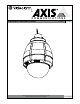
for COMMUNICATIONS MODEL: PRODUCT INSTRUCTIONS Before attempting to connect or operate this product, please read these instructions completely.
IMPORTANT SAFEGUARDS 1. Read Instructions - All the safety and operating instructions SAFETY PRECAUTIONS should be read before the unit is operated. 2. Retain Instructions - The safety and operating instructions should be retained for future reference. ! 3. Heed Warnings - All warnings on the unit and in the operating instructions should be adhered to. 4. Follow Instructions - All operating and user instructions should be followed. 5.
! Electrical Specifications Power 24VAC Class 2 Only English Español Français Deutsch Portuguese Italiano Content of Box 25734 Outdoor Housing (Clear) 35542 Outdoor Only (Tinted) Total Power: 89 Watts Heater: 50 Watts Blower: 2 Watts Camera Power: Up to 37 watts Input Connectors (Outdoor Units): (1) BNC (Analog Video) (2) Screw-Down Connectors (Power/Alarms) (1) RJ45 (Data) Energía Total: 89 vatios Calentador: 50 vatios Soplador: 2 vatios Energía De la Cámara fotográfica: Up to 37 vatios Conecta
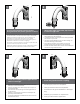
1 2 Wrap Teflon tape around the pipe threads to ensure a tight seal. Securely mount bracket to wall. Pull wiring through bracket and position grommet as shown. • Con seguridad soporte del montaje a emparedar. Tire del cableado a través del soporte y del ojal de la posición según lo demostrado. • Solidement parenthèse de bâti à murer. Tirez le câblage par la parenthèse et le canon isolant de position comme montré. • Sicher Einfassung Haltewinkel wall.
Loop the lanyard over the set screw to temporarily hold housing. • Coloque el acollador sobre el tornillo de presión para celebrar temporalmente la cubierta. • Faites une boucle la lanière au-dessus de la vis de réglage pour tenir temporairement le logement. • Schlingen Sie die Abzuglinie über der Klemmschraube, um Gehäuse vorübergehend zu halten. • Dê laços no colhedor sobre o parafuso de fixação para prender temporariamente a carcaça.
9 RJ45 24VAC 1 2 3 4 Camera Camera Heater/Blower Heater/Blower SNC-RZ25/SNC-RZ550 Red Orange Yellow Green 18 Watts 25 Watts 52 Watts 1/0 Alarm 1 Alarm 2 Alarm 3 Common 1 2 3 4 Blue Violet Gray White RJ45 Make the appropriate male and female connections. Indoor model does not include pre-run cables. • Haga las conexiones masculinas y femeninas apropiadas. El modelo de interior no incluye pre-funciona los cables. • Établissez les rapports masculins et femelles appropriés.
17 12 Axis 213 (3) #8x3/8” (13mm) ½" Mounting Plate (26mm) 1" Captive Screw (52mm) 2" MOUNTING HOLE Install the camera to the mounting plate with (2) #10 screws and lock washers provided. Place (3) #8x3/8” screws on the spacers and align the mounting slots. Slide on plate and camera then secure. • Instale la cámara fotográfica a la placa de montaje con (2) los tornillos #10 y las arandelas de cerradura proporcionadas.
14 Axis 215 ½" 1" 1" Mounting Holes Mounting Holes 2" Attach camera to quick release plate as shown. Use spacers to assemble (4) 3” legs. Secure camera into position. • Una la cámara fotográfica a la placa rápida del lanzamiento según lo demostrado. Utilice los espaciadores para montar (4) las piernas del 3". Asegure la cámara fotográfica en la posición. • Attachez l'appareil-photo au plat rapide de dégagement comme montré. Employez les entretoises pour assembler (4) des jambes de 3".
20 17 Connection Module 3mm Screw Power Board To remove thethe power board,path use screwdriver to release fasteners applying to sides while pulling out. This is what typical of illumination willplastic look like withby the settingpressure at 30 degrees. Attach connection module as shown. Attach this assembly to the housing using (1) 6-32x3/8” screw and star washer.
19 Axis 233D Remove 24Vac to 12VDC power board located inside of housing, attach 2 “L ” brackets to mounting plate. Connect Pan tilt with hardware provided. • Quite 24Vac al tablero de energía 12VDC situado dentro de la cubierta, una 2 "L" soportes a la placa de montaje. Conecte la inclinación de la cacerola con la placa de montaje con el hardware proporcionado. • Enlevez 24Vac sur carte d'alimentation 12VDC situé à l'intérieur de du logement, attachez 2 "L" parenthèses au plat de support.
22 21 Tab Connect Lanyard to trim ring assembly. • Conecte el acollador con el montaje del anillo del ajuste. • Reliez la lanière à l'anneau d'équilibre. • Schließen Sie Abzuglinie an Ordnung Ring an. • Conecte o colhedor ao conjunto do anel da guarnição. • Colleghi la cordicella al complessivo dell'anello della cornice. Align the arrows on the outside of the dome and lock. • Alinee las flechas en el exterior de la bóveda y trábese.
Replacement Parts List 25734 16 9 11 8 4 10 6 5 7 6 3 2 1 Part Number Description 1 RPFD7015 Lower Trim Ring 2 RC7AT Tinted Replacement Capsule RC7AC Clear Replacement Capsule 3 RPFD703 Dome Clamping Bracket 4 RPFD072 24 Vac Heater 5 RPFD080 (12 Vdc) Blower (Used In 24v Housings) 6 RPFD060 Camera Bracket 7 RPRH707 Connection Pcb 8 RPFD040 Housing Hardware 9 RPFD709 Housing Top 10 RPNET02 Network Housing Power Board 11 RP46PKH2095 Network Camera Bracket 12 RP