
- Axis User's Manual Network Camera 2120


AXIS 2120 User’s Manual Physical Description
9
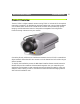
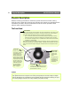
The Rear Panel
Note: The power supply for your AXIS 2120 is country specific. Please check that you are using the cor-
rect type. See page 10.
Power Supply
Connector
A single Jack socket
(PS-D) for connection
of the AXIS 2120
power supply. The ter-
minal block connector
provides an auxiliary
connection point for
AC or DC power to the
unit.
Power Indicator
Normally lit when
power is applied. If it is
not lit, or it flashes,
there is a problem with
the AXIS 2120 external
power supply.
Network Indicator
After completion of the startup and self test routines, this
multi-colored indicator flashes independently, as follows:
• yellow - activity on a 10Mbps network
• green - activity on a 100Mbps network
• red - no physical connection to the network
Network Connector
The AXIS 2120 is designed for
10 Mbps Ethernet and 100
Mbps Fast Ethernet networks
and connects to the network
via a twisted pair category 5
cable (10baseT and
100baseTX), terminated using
a standard RJ-45 connector.
Supporting NWAY, the AXIS
2120 detects the speed of the
local network segment and
varies the speed of data com-
munication accordingly
(between 10 Mbps and 100
Mbps)..
I/O Connector
Provides the physical interface to a digital output, and a single digital photo-cou-
pled input that is used for connecting a variety of external alarm devices to the AXIS
2120 including, IR-sensors, switches and alarm relays. In combination with the con-
figurable alarm facilities, you can quickly develop a variety of security applications
that are triggered on time - or alarm based - events. The connector can also be uti-
lized as an alternative connection point for DC power to the unit. For pinout infor-
mation, refer to Appendix D - The Unit Connectors.
RS-232 Serial
Connector
The serial connector provides
the RS-232 interface for con-
necting a modem, or the con-
nection for the AXIS 2191
Audio Module. For pinout
information, see Appendix D -
The Unit Connectors.
DC-Iris Connector
With the DC-Iris cable con-
nected to the lens upon
delivery, this socket pro-
vides the power and elec-
tronic signalling to the lens
of the AXIS 2120.
For instructions on how to
change the DC Iris settings,
refer to Adjusting the
DC-Iris Settings, on page