
- AXIS User's Manual Network Camera 210/211
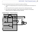
Table Of Contents
43
AXIS 210/211 - The I/O Terminal Connector
Connect input/output devices to the terminal connector as follows:
1. Loosen the corresponding screw on top of the pin (see above for the correct pin to
use).
2. Push the cable into the connector and secure it by fastening the screw.
3. Once devices are connected, connect the terminal connector to the camera,
making sure that all cables are securely fastened.
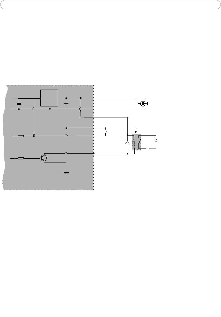
Schematic Diagram - Terminal Connectors
o
z
z
o
o
o
oo
AXIS 210/211 camera
3.3V
PS-K 9V
e.g. push
Device
z
4
o
3
o
Switch
Mode
Power
Supply
o
1
o
o
Relay
GND
+
2