
User Manual
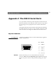
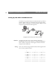
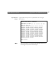
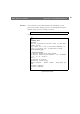
Table Of Contents
- Cover
- Section 1 Introduction
- Section 2 Installing the AXIS 240
- Section 3 Assigning an IP Address
- Section 4 Configuring the AXIS 240
- Section 5 Using the AXIS 240
- Appendix A Troubleshooting
- Appendix B The Parameter List
- Appendix C Updating the Software
- Appendix D Technical Specifications
- Appendix E The Auxiliary IO Port
- Appendix F The RS232 Serial Ports
- Appendix G Camera Applications
- Appendix H CRON Script Command Reference

Appendix F: The RS232 Serial Ports AXIS 240 Users Manual
92
Setting Up the AXIS 240 Modem Server
A modem server provided within your AXIS 240 makes it possible to
transmit snapshot images over the PSTN. By connecting the AXIS
240 to a modem, it is possible to download snapshot images to remote
computers using standard modem equipment.
Configuration of the serial port for modem connection
RTS/CTS
The AXIS 240 modem server utilizes hardware (RTS/CTS)
handshaking. In this mode of operation, a straight-through RS232
cable is all that is required for connecting the modems to both the
computer and the AXIS 240.
Wiring
This is the common wiring schedule for RS232 cables supplied with
most of todays popular modems:
Signal name Server pin Modem pin
CD 1 8
-RXD 2 3
-TXD 3 2
DTR 4 20
GND 5 7
NC 6 6
RTS 7 4
CTS 8 5
RI 9 22