
User Manual
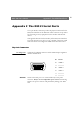
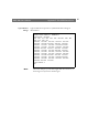
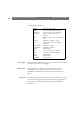
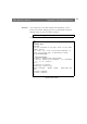
Table Of Contents
- Cover
- Section 1 Introduction
- Section 2 Installing the AXIS 240
- Section 3 Assigning an IP Address
- Section 4 Configuring the AXIS 240
- Section 5 Using the AXIS 240
- Appendix A Troubleshooting
- Appendix B The Parameter List
- Appendix C Updating the Software
- Appendix D Technical Specifications
- Appendix E The Auxiliary IO Port
- Appendix F The RS232 Serial Ports
- Appendix G Camera Applications
- Appendix H CRON Script Command Reference

AXIS 240 Users Manual Appendix F: The RS232 Serial Ports
91
Appendix F The RS232 Serial Ports
Two 9 pin D-sub connectors provides the physical connection for the
RS232 serial interface of the AXIS 240. These connectors are provided
for connecting accessory equipment such as modems and Pan/Tilt
devices.
This appendix discusses the functionality of the RS232 serial interface.
It provides instructions on how to set up a modem connection, install
a Pan/Tilt device and configure the AXIS 240 for Pan/Tilt control.
Physical Connector
Pin Assignment
A diagram of an RS232 connector and the AXIS 240 pin assignment
table are detailed below.
Caution!
GND on the serial port is not connected directly to the power
connector. Always use two independent power sources! Connecting
GND to the power connector will permanently damage your AXIS
240.
Pin Function
1 CD
2 - RXD
3 - TXD
4 DTR
5 GND
6 NC
7 RTS
8 CTS
9 RI
4
2
5
6
13
7
89