
User Manual
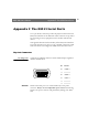
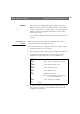
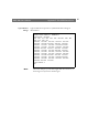
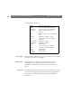
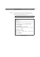
Table Of Contents
- Cover
- Section 1 Introduction
- Section 2 Installing the AXIS 240
- Section 3 Assigning an IP Address
- Section 4 Configuring the AXIS 240
- Section 5 Using the AXIS 240
- Appendix A Troubleshooting
- Appendix B The Parameter List
- Appendix C Updating the Software
- Appendix D Technical Specifications
- Appendix E The Auxiliary IO Port
- Appendix F The RS232 Serial Ports
- Appendix G Camera Applications
- Appendix H CRON Script Command Reference

Appendix E: The Auxiliary IO Port AXIS 240 Users Manual
90
This table describes each digital input text string:
Note:
❏ The way in which you use the auxiliary connector is of course, for
you to decide. Axis does not provide any application software, but
instead allows you to determine how this connector is best
utilized. Naturally, we would be more than pleased to learn of any
interesting applications that you might develop!
String Description
input: Input reference
(Input 1= pin 6, Input 2 = pin 7,
Input 3 = pin 4, Input 4 = pin 5)
current Current port status
(Logical high = 1, Logical low = 0)
last Result of previous read operation
pulse The number of logical one-to-zero transi-
tions on the I/O pin, since the last read.
time_of_change The time of the last change on the input pin.