
User Manual
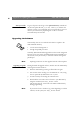
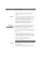

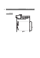
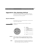
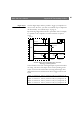
Table Of Contents
- Cover
- Section 1 Introduction
- Section 2 Installing the AXIS 240
- Section 3 Assigning an IP Address
- Section 4 Configuring the AXIS 240
- Section 5 Using the AXIS 240
- Appendix A Troubleshooting
- Appendix B The Parameter List
- Appendix C Updating the Software
- Appendix D Technical Specifications
- Appendix E The Auxiliary IO Port
- Appendix F The RS232 Serial Ports
- Appendix G Camera Applications
- Appendix H CRON Script Command Reference

AXIS 240 Users Manual Appendix E: The Auxiliary IO Port
89
Digital Inputs
The four digital
inputs make it possible to trigger your snapshots on
chosen events. However, you must use a CRON script to implement
this functionality. See CRON Script on page 51.
By connecting a digital microcircuit to a particular door for example,
it is possible to take a snapshot on each occasion that it opens or
closes.
Schematic diagram of the AXIS 240 Auxiliary Connector
- displaying a possible application
Status information for each of the digital inputs is presented within a
text string. The status of the inputs can be read by clicking on the
input.txt link in the IO file URL. The string will amongst other
things define the time and duration of the last trigger event for each
input:
input:1 current:0 last:1 pulse:2 time_of_change:12.22
input:2 current:1 last:0 pulse:6 time_of_change:14.43
input:3 current:0 last:1 pulse:1 time_of_change:09.13
input:4 current:0 last:1 pulse:4 time_of_change:12.25
o
o
CPU
.
o
x
6
8
o
o
Digital input 1
GND
Relay
Switch
5V
Mains Power
o
o
o
o
o o
24V DC
o
o
7
o
Digital input 2
.
.
Micro-switched door
.
Infra-red switch
AXIS 240
Aux.
Con.
Appliance
o o
Relay +
Relay -
Optional
Relay
Switch
1
2