
User Manual

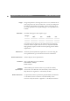
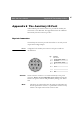
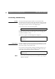
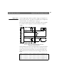
Table Of Contents
- Cover
- Section 1 Introduction
- Section 2 Installing the AXIS 240
- Section 3 Assigning an IP Address
- Section 4 Configuring the AXIS 240
- Section 5 Using the AXIS 240
- Appendix A Troubleshooting
- Appendix B The Parameter List
- Appendix C Updating the Software
- Appendix D Technical Specifications
- Appendix E The Auxiliary IO Port
- Appendix F The RS232 Serial Ports
- Appendix G Camera Applications
- Appendix H CRON Script Command Reference

AXIS 240 Users Manual Appendix E: The Auxiliary IO Port
87
Appendix E The Auxiliary IO Port
A Mini-DIN 8-pole external connector is provided for auxiliary IO
connections to the AXIS 240. This appendix discusses the additional
functionality that this connector provides.
Physical Connection
The auxiliary IO connector provides the interface to one relay switch
output and four digital inputs.
Pinout
A diagram for the auxiliary IO connector and a pinout table are
detailed below:
Caution!
GND on the IO connector is not connected directly to the power
connector. Always use two independent power sources! Connecting
GND to the power connector will permanently damage your AXIS
240.
Note:
❏ The inputs are connected between the input pin and GND, and
must be potential free switches, i.e. push button switches or relay
switches. The input switch circuit current is 1mA.
Pin Function
1 Relay switch
(Max 24V AC/DC, 100mA)
2 Relay switch
(Max 24V AC/DC, 100mA)
3 NC
4 Input 3
5 Input 4
6 Input 1
7 Input 2
8 GND
3
2
7
4
1
5
8
6