
User Manual
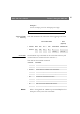
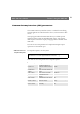
Table Of Contents
- Cover
- Section 1 Introduction
- Section 2 Installing the AXIS 240
- Section 3 Assigning an IP Address
- Section 4 Configuring the AXIS 240
- Section 5 Using the AXIS 240
- Appendix A Troubleshooting
- Appendix B The Parameter List
- Appendix C Updating the Software
- Appendix D Technical Specifications
- Appendix E The Auxiliary IO Port
- Appendix F The RS232 Serial Ports
- Appendix G Camera Applications
- Appendix H CRON Script Command Reference

Section 5: Using the AXIS 240 AXIS 240 Users Manual
54
Input and Boot
Field
The sixth field consists of a character array. It is optional and defines
the input and boot trigger functions.
You can program the AXIS 240 to trigger at startup or on the logical
states present on the Control button and digital input ports, using the
trigger variables
BOOT, B, I1, I2, I3 and I4 respectively. The B, I1, I2,
I3 and I4 trigger variables must be proceeded by an activate
condition,
/, \, 0 or 1, to indicate when the trigger variable is
activated.
This table outlines the available trigger variables and their possible
combinations:
Note:
❏ The AXIS 240 polls the input ports every 0.2 seconds. Thus,
more rapid logical transitions will not be detected.
By combining the trigger variables using the logical AND function, &,
you can develop complex triggering mechanisms.
Example 1
Activate on Control button transition from high to low and Input
port 1 high.
Trigger Variable Description
BOOT Activate at startup.
\B Activate after high-low logical transition of Control button.
/B Activate after low-high logical transition of Control button.
1B Activate when Control button is logically high (pressed).
0B Activate when Control button is logically low (released).
\I1 Activate after high-low logical transition on Input port 1.
/I2 Activate after low-high logical transition on Input port 2.
1I3 Activate when Input port 3 is logically high.
0I4 Activate when Input port 4 is logically low.
... etc.
\B&1I1