
User Manual

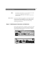
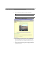
Table Of Contents
- Cover
- Section 1 Introduction
- Section 2 Installing the AXIS 240
- Section 3 Assigning an IP Address
- Section 4 Configuring the AXIS 240
- Section 5 Using the AXIS 240
- Appendix A Troubleshooting
- Appendix B The Parameter List
- Appendix C Updating the Software
- Appendix D Technical Specifications
- Appendix E The Auxiliary IO Port
- Appendix F The RS232 Serial Ports
- Appendix G Camera Applications
- Appendix H CRON Script Command Reference

Installing the AXIS 240 AXIS 240 Users Manual
14
Connectors
Camera Inputs
The AXIS 240 is equipped with 4 CAM coax/BNC connectors and
one S-video connector (Y/C). The inputs are autosensing for the video
format used in the connected cameras, i.e. NTSC, PAL, Black/white
50Hz or Black/white 60Hz.
Dip Switches
Each of the CAM coax inputs has a 75 ohm terminator resistor.
Normally, the resistors are switched on with the corresponding dip
switches down. If the AXIS 240 is connected in parallel with other
equipment, you are recommended to turn off the resistors using the
dip switches. Otherwise, the picture quality might be reduced.
I/O
A Mini-DIN 8-pole external connector with four inputs for auxiliary
connection to the AXIS 240. The functionality of this connector is
fully discussed in Appendix E - The Auxiliary IO Port.
Pan/Tilt
Modem
Two 9 pin D-sub connectors provides RS232 serial connections,
normally to a Pan/Tilt device and a modem. The connectors are
discussed in detail in Appendix F - The RS232 Serial Ports.
10BaseT
10BaseT (RJ-45) twisted pair Ethernet connector for connection to
the network.
Power
Jack socket (PS-D) for connection of AXIS 240 power supply. An
alternative power connector is also provided.
Caution!
❏ The power supply delivered with your AXIS 240 is country
specific. Please check that the type of power supply you are using
is correct against the list on page 12.