
Instructions


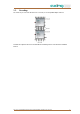


Table Of Contents

Operation Instructions | SES 5532-19 | Programmable Unicable II Multiswitch
8 2020-06-30 | Technical improvements, changes in design, printing- and other errors expected.
3. Electrical installation
3.1. Connections
1 Inputs for LNB
V/L, V/H, H/L and H/H for Quattro LNB
V and H left for 1st wideband LNB | V and H right for 2nd wideband LNB
2 Terrestrial input
3 Equipotential bonding connection
4 Unicable II output
5 Legacy/Unicable II output
6 SAT cascade outputs
7 TERR cascade output
For the installation, use a high-quality coaxial cable and F plug suitable for the satellite reception and with
screening attenuation of at least 90 dB.
Connections which are not used must be terminated with terminating resistors CFA 11-00.
Use antenna sockets which are suitable for Unicable II. We recommend the programmable antenna sockets
SSD 6-xx.
To avoid dangerous overvoltages (attention: risk of fire/death), the devices must be connected to the
equipotential bonding. Use the equipotential bonding connection attached to the device.
Important: When installing, make sure that EN 60728-11 is complied with!