
Datasheet


Anhang
Annex
Stand: März 2010 – Konstruktions- und Typenänderung vorbehalten
state of the art: March 2010 – Reserving change in design and type
Seite 199
Page 199
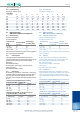
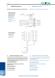
7 Erdung und Potentialausgleich
der Antennenanlage (nach EN 50083 - 1)
Der Mast ist auf kürzestmöglichem Weg über einen Erdungsleiter mit
Erde zu verbinden. Die Aussenleiter aller von der Antenne niederge-
führten Koaxialkabel sind über einen Potentialausgleichsleiter mit dem
Mast oder dem Erdungsleiter zu verbinden. Schleifenbildungen sind zu
vermeiden. Erdungsleiter sind geradlinig und senkrecht auszuführen.
7.0.1 Erdungsleitungen (Massivdraht):
7.0.2 Potentialausgleichsleitungen (Massivdraht):
Ausführungsbeispiele sind der EN 50083 - 1 zu entnehmen.
Material Querschnitt Ausführung
Kupfer ≥ 16 mm
2
blank oder isoliert
Aluminium
≥ 25 mm
2
isoliert
Stahl ≥ 50 mm
2
Material Querschnitt Ausführung
Kupfer ≥ 4 mm
2
blank oder isoliert
7 Grounding and equipotential bonding
of the antenna installation (according to EN 50083 -
1)
The tower has to be connected to ground via a ground conductor at
shortest possible distance. The outside conductors of all coaxial
cables lead down from the antenna have to be connected to the tower
with an equipotential bonding conductor or to the ground conductor.
Looping has to be avoided. Ground conductors have to be laid in
straight lines and vertically.
7.0.1 Ground lines (solid wire):
7.0.2
Equipotential bonding lines (solid wire):
EN 50083 - 1 offers examples of these types.
Material Cross section Type
Copper ≥ 16 mm
2
uninsulated or insulated
Aluminium
≥ 25 mm
2
insulated
Steel ≥ 50 mm
2
Material Cross section Type
Copper ≥ 4 mm
2
uninsulated or insulated