
Datasheet

108-98007 Rev A
All specications subject to change. Consult Tyco Electronics for latest specications. 9 of 12
Telecom-, Signal and RF Relays
D2n V23105 Relay
AXICOM
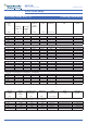
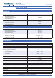
Insulation
Insulation resistance at 500 Vdc
> 10
9
Ω
Dielectric test voltage (1 min)
between coil and contacts
between adjacent contact sets
between open contacts
1050 Vrms
750 Vrms
750 Vrms
Surge voltage resistance
according to FCC 68 (10 / 700 µs)
between coil and contacts
between adjacent contact sets
between open contactss
1500 V
1500 V
1500 V
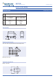
High Frequency Data
Capacitance
between coil and contacts
between adjacent contact sets
between open contacts
max. 4 pF
max. 2 pF
max. 2 pF
RF Characteristics
Isolation at 100 / 900 MHz
Insertion loss at 100 / 900 MHz
V.S.W.R. at 100 / 900 MHz
-39.0 dB / -20.7 dB
-0.02 dB / -0.27 dB
1.04 / 1.40
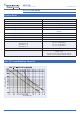
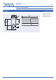
General Data
Operate time at U
nom
typ. / max.
5 ms / 6 ms
Release time without diode in parallel, typ. / max.
4 ms / 4 ms
Release time with diode in parallel, typ. / max.
5 ms / 5 ms
Bounce time at closing contact, typ. / max.
3 ms / 5 ms
Maximum switching rate without load
50 operations/s
Ambient temperature
150 and 200 mW coil
400 mW coil
500 mW coil
-25 °C ... +85 °C
-25 °C ... +75 °C
-25 °C ... +60 °C
Thermal resistance
< 85 K/W
Maximum permissible coil temperature
115 °C
Vibration resistance (function)
10 g
10 to 55 Hz
Shock resistance, half sinus, 11 ms
10 g (function)
50 g (damage)
Degree of protection / Environmental protection
immersion cleanable, IP 67 / RT III
Needle flame test
application time 10 s
Mounting position
any
Processing information
Ultrasonic cleaning is not recommended
Weight (mass)
max. 6 g
Terminal coating
SnCu 0.7
Resistance to soldering heat
265 °C / 10 s
All data refers to 23 °C unless otherwise specied.