
Datasheet
08-2012, Rev. 0812
www.te.com
© 2012 Tyco Electronics Corporation,
a TE Connectivity Ltd. company
Datasheets and product specification
according to IEC 61810-1 and to be used
only together with the ‘Definitions’ section.
Datasheets and product data is subject to the
terms of the disclaimer and all chapters of
the ‘Definitions’ section, available at
http://relays.te.com/definitions
Datasheets, product data, ‘Definitions’ sec-
tion, application notes and all specifications
are subject to change.
2
AXICOM
Signal Relays
MT2 Relay
(Continued)
Coil Data (continued) Coil Data (continued)
Coil operative range graphs
U
nom
Nominal coil voltage
U
max
Upper limit of the operative range of the coil voltage (limiting
voltage) when coils are continously energized
U
op. min.
Lower limit of the operative range of
the coil voltage (reliable operate voltage)
U
rel. min.
Lower limit of the operative range of
the coil voltage (reliable release voltage)
Insulation Data
Initial dielectric strength
between open contacts 750V
rms
between contact and coil 1050V
rms
between adjacent contacts 750V
rms
Initial surge withstand voltage
between open contacts 1500V
between contact and coil 1500V
between adjacent contacts 1500V
Initial insulation resistance at 500VDC > 10
9
Ω
Capacitance
between open contacts max. 2pF
between contact and coil max. 4pF
between adjacent contacts max. 2 pF
RF Data
Isolation at 100MHz/900MHz -31.8dB/-14.2dB
Insertion loss at 100MHz/900MHz -0.02dB/-0.97dB
Voltage standing wave ratio (VSWR)
at 100MHz/900MHz 1.03/1.31
Other Data
Material compliance: EU RoHS/ELV, China RoHS, REACH, Halogen content
refer to the Product Compliance Support Center at
www.te.com/customersupport/rohssupportcenter
Ambient temperature -55 to +85°C
Category of environmental protection
IEC 61810 RT III - immersion cleanable
Degree of protection, IEC 60529 IP 67
Vibration resistance (functional) 10g, 10 to 500Hz
Shock resistance (functional)
IEC 60068-2-27 (half sine) 10g/30g
Shock resistance (destructive) 500g
Terminal type PCB-THT
Weight max. 5g
Resistance to soldering heat THT
IEC 60068-2-20 265 °C / 10 s
Ultrasonic cleaning not recommended
Packaging unit 1000 pcs.
108-98006 Rev. E
All specifications subject to change. Consult Tyco Electronics for latest specifications. 5 of 11
MT2 Relay
Telecom-, Signal and RF Relays
AXICOM
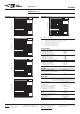
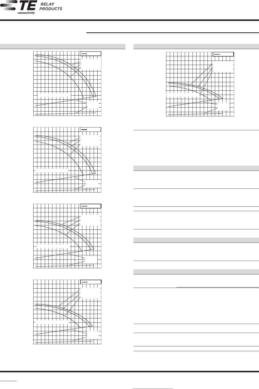
Coil Operating Range
U
nom
= Nominal coil voltage
U
max.
= Upper limit of the operative range of the coil voltage (limiting
voltage) when coils are continously energized
U
op. min.
= Lower limit of the operative range of
the coil voltage (reliable operate voltage)
U
rel. min.
= Lower limit of the operative range of
the coil voltage (reliable release voltage)
0.0
0.2
0.4
0.6
0.8
1.0
1.2
1.4
1.6
1.8
2.0
2.2
2.4
2.6
2.8
3.0
3.2
-60-50 -40-30 -20-10 0102030405060708090 100 110 120
150 mW coil
0
0.2
0.4
0.6
0.8
1
1.2
1.4
1.6
1.8
2
2.2
2.4
2.6
2.8
3
-60-50 -40-30 -20-10 0102030405060708090 100 110 120
200 mW coil
0.0
0.2
0.4
0.6
0.8
1.0
1.2
1.4
1.6
1.8
2.0
2.2
2.4
2.6
2.8
3.0
-60-50 -40-30 -20-10 0102030405060708090 100 110 120
300 mW coil
0.0
0.2
0.4
0.6
0.8
1.0
1.2
1.4
1.6
1.8
2.0
2.2
2.4
2.6
2.8
3.0
-60-50 -40-30 -20-10 0102030405060708090 100 110120
400 mW coil
0.0
0.2
0.4
0.6
0.8
1.0
1.2
1.4
1.6
1.8
2.0
2.2
2.4
2.6
2.8
3.0
-60-50 -40-30 -20-10 0102030405060708090 100 110 120
550 mW coil
U
max.
at 0 A
Umax. at 2 x 2 A
Umax. at 2 x 1 A
Unom. nominal coil voltage
Uop. min.
Urel. min.
Ambient Temperature [°C]
Coil Voltage [U/U
nom]
Umax. at 0 A
Umax. at 2 x 2 A
U
max.
at 2 x 1 A
Uop. min.
Urel. min.
Ambient Temperature [°C]
Coil Voltage [U/Unom
]
Umax. at 0 A
Umax. at 2 x 2 A
Umax. at 2 x 1 A
Unom. nominal coil voltage
Uop. min.
Urel. min.
Umax. at 0 A
Umax. at 2 x 2 A
Umax. at 2 x 1 A
Unom. nominal coil voltage
Uop. min.
Urel. min.
Umax. at 0 A
Umax. at 2 x 2 A
Umax. at 2 x 1 A
Unom. nominal coil voltage
Uop. min.
Urel. min.
Ambient Temperature [°C]
Coil Voltage [U/U
nom
]
Ambient Temperature [°C]
Coil Voltage [U/U
nom
]
Ambient Temperature [°C]
Coil Voltage [U/Unom]
150 mW
200 mW
300 mW
400 mW
550 mW
Unom. nominal coil voltage
108-98006 Rev. E
All specifications subject to change. Consult Tyco Electronics for latest specifications. 5 of 11
MT2 Relay
Telecom-, Signal and RF Relays
AXICOM
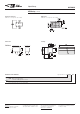
Coil Operating Range
U
nom
= Nominal coil voltage
U
max.
= Upper limit of the operative range of the coil voltage (limiting
voltage) when coils are continously energized
U
op. min.
= Lower limit of the operative range of
the coil voltage (reliable operate voltage)
U
rel. min.
= Lower limit of the operative range of
the coil voltage (reliable release voltage)
0.0
0.2
0.4
0.6
0.8
1.0
1.2
1.4
1.6
1.8
2.0
2.2
2.4
2.6
2.8
3.0
3.2
-60-50 -40-30 -20-10 0102030405060708090 100 110 120
150 mW coil
0
0.2
0.4
0.6
0.8
1
1.2
1.4
1.6
1.8
2
2.2
2.4
2.6
2.8
3
-60-50 -40-30 -20-10 0102030405060708090 100 110 120
200 mW coil
0.0
0.2
0.4
0.6
0.8
1.0
1.2
1.4
1.6
1.8
2.0
2.2
2.4
2.6
2.8
3.0
-60-50 -40-30 -20-10 0102030405060708090 100 110 120
300 mW coil
0.0
0.2
0.4
0.6
0.8
1.0
1.2
1.4
1.6
1.8
2.0
2.2
2.4
2.6
2.8
3.0
-60-50 -40-30 -20-10 0102030405060708090 100 110120
400 mW coil
0.0
0.2
0.4
0.6
0.8
1.0
1.2
1.4
1.6
1.8
2.0
2.2
2.4
2.6
2.8
3.0
-60-50 -40-30 -20-10 0102030405060708090 100 110 120
550 mW coil
U
max.
at 0 A
Umax. at 2 x 2 A
Umax. at 2 x 1 A
U
nom.
nominal coil voltage
Uop. min.
Urel. min.
Ambient Temperature [°C]
Coil Voltage [U/U
nom]
U
max.
at 0 A
Umax. at 2 x 2 A
U
max.
at 2 x 1 A
Uop. min.
Urel. min.
Ambient Temperature [°C]
Coil Voltage [U/Unom
]
Umax. at 0 A
Umax. at 2 x 2 A
Umax. at 2 x 1 A
Unom. nominal coil voltage
Uop. min.
Urel. min.
Umax. at 0 A
Umax. at 2 x 2 A
Umax. at 2 x 1 A
Unom. nominal coil voltage
Uop. min.
Urel. min.
Umax. at 0 A
Umax. at 2 x 2 A
Umax. at 2 x 1 A
Unom. nominal coil voltage
Uop. min.
Urel. min.
Ambient Temperature [°C]
Coil Voltage [U/U
nom
]
Ambient Temperature [°C]
Coil Voltage [U/U
nom
]
Ambient Temperature [°C]
Coil Voltage [U/Unom]
150 mW
200 mW
300 mW
400 mW
550 mW
Unom. nominal coil voltage
108-98006 Rev. E
All specifications subject to change. Consult Tyco Electronics for latest specifications. 5 of 11
MT2 Relay
Telecom-, Signal and RF Relays
AXICOM
Coil Operating Range
U
nom
= Nominal coil voltage
U
max.
= Upper limit of the operative range of the coil voltage (limiting
voltage) when coils are continously energized
U
op. min.
= Lower limit of the operative range of
the coil voltage (reliable operate voltage)
U
rel. min.
= Lower limit of the operative range of
the coil voltage (reliable release voltage)
0.0
0.2
0.4
0.6
0.8
1.0
1.2
1.4
1.6
1.8
2.0
2.2
2.4
2.6
2.8
3.0
3.2
-60-50 -40-30 -20-10 0102030405060708090 100 110 120
150 mW coil
0
0.2
0.4
0.6
0.8
1
1.2
1.4
1.6
1.8
2
2.2
2.4
2.6
2.8
3
-60-50 -40-30 -20-10 0102030405060708090 100 110 120
200 mW coil
0.0
0.2
0.4
0.6
0.8
1.0
1.2
1.4
1.6
1.8
2.0
2.2
2.4
2.6
2.8
3.0
-60-50 -40-30 -20-10 0102030405060708090 100 110 120
300 mW coil
0.0
0.2
0.4
0.6
0.8
1.0
1.2
1.4
1.6
1.8
2.0
2.2
2.4
2.6
2.8
3.0
-60-50 -40-30 -20-10 0102030405060708090 100 110120
400 mW coil
0.0
0.2
0.4
0.6
0.8
1.0
1.2
1.4
1.6
1.8
2.0
2.2
2.4
2.6
2.8
3.0
-60-50 -40-30 -20-10 0102030405060708090 100 110 120
550 mW coil
U
max.
at 0 A
Umax. at 2 x 2 A
Umax. at 2 x 1 A
Unom. nominal coil voltage
Uop. min.
Urel. min.
Ambient Temperature [°C]
Coil Voltage [U/U
nom]
Umax. at 0 A
Umax. at 2 x 2 A
U
max.
at 2 x 1 A
Uop. min.
Urel. min.
Ambient Temperature [°C]
Coil Voltage [U/Unom
]
Umax. at 0 A
Umax. at 2 x 2 A
Umax. at 2 x 1 A
Unom. nominal coil voltage
Uop. min.
Urel. min.
Umax. at 0 A
Umax. at 2 x 2 A
Umax. at 2 x 1 A
Unom. nominal coil voltage
Uop. min.
Urel. min.
Umax. at 0 A
Umax. at 2 x 2 A
Umax. at 2 x 1 A
Unom. nominal coil voltage
Uop. min.
Urel. min.
Ambient Temperature [°C]
Coil Voltage [U/U
nom
]
Ambient Temperature [°C]
Coil Voltage [U/U
nom
]
Ambient Temperature [°C]
Coil Voltage [U/Unom]
150 mW
200 mW
300 mW
400 mW
550 mW
Unom. nominal coil voltage
108-98006 Rev. E
All specifications subject to change. Consult Tyco Electronics for latest specifications. 5 of 11
MT2 Relay
Telecom-, Signal and RF Relays
AXICOM
Coil Operating Range
U
nom
= Nominal coil voltage
U
max.
= Upper limit of the operative range of the coil voltage (limiting
voltage) when coils are continously energized
U
op. min.
= Lower limit of the operative range of
the coil voltage (reliable operate voltage)
U
rel. min.
= Lower limit of the operative range of
the coil voltage (reliable release voltage)
0.0
0.2
0.4
0.6
0.8
1.0
1.2
1.4
1.6
1.8
2.0
2.2
2.4
2.6
2.8
3.0
3.2
-60-50 -40-30 -20-10 0102030405060708090 100 110 120
150 mW coil
0
0.2
0.4
0.6
0.8
1
1.2
1.4
1.6
1.8
2
2.2
2.4
2.6
2.8
3
-60-50 -40-30 -20-10 0102030405060708090 100 110 120
200 mW coil
0.0
0.2
0.4
0.6
0.8
1.0
1.2
1.4
1.6
1.8
2.0
2.2
2.4
2.6
2.8
3.0
-60-50 -40-30 -20-10 0102030405060708090 100 110 120
300 mW coil
0.0
0.2
0.4
0.6
0.8
1.0
1.2
1.4
1.6
1.8
2.0
2.2
2.4
2.6
2.8
3.0
-60-50 -40-30 -20-10 0102030405060708090 100 110120
400 mW coil
0.0
0.2
0.4
0.6
0.8
1.0
1.2
1.4
1.6
1.8
2.0
2.2
2.4
2.6
2.8
3.0
-60-50 -40-30 -20-10 0102030405060708090 100 110 120
550 mW coil
Umax. at 0 A
Umax. at 2 x 2 A
U
max.
at 2 x 1 A
Unom. nominal coil voltage
Uop. min.
Urel. min.
Ambient Temperature [°C]
Coil Voltage [U/U
nom]
U
max.
at 0 A
U
max.
at 2 x 2 A
Umax. at 2 x 1 A
U
op. min.
Urel. min.
Ambient Temperature [°C]
Coil Voltage [U/Unom
]
U
max.
at 0 A
U
max.
at 2 x 2 A
Umax. at 2 x 1 A
Unom. nominal coil voltage
Uop. min.
Urel. min.
Umax. at 0 A
Umax. at 2 x 2 A
Umax. at 2 x 1 A
Unom. nominal coil voltage
Uop. min.
Urel. min.
Umax. at 0 A
Umax. at 2 x 2 A
Umax. at 2 x 1 A
Unom. nominal coil voltage
Uop. min.
U
rel. min.
Ambient Temperature [°C]
Coil Voltage [U/U
nom
]
Ambient Temperature [°C]
Coil Voltage [U/U
nom
]
Ambient Temperature [°C]
Coil Voltage [U/Unom]
150 mW
200 mW
300 mW
400 mW
550 mW
Unom. nominal coil voltage
108-98006 Rev. E
All specifications subject to change. Consult Tyco Electronics for latest specifications. 5 of 11
MT2 Relay
Telecom-, Signal and RF Relays
AXICOM
Coil Operating Range
U
nom
= Nominal coil voltage
U
max.
= Upper limit of the operative range of the coil voltage (limiting
voltage) when coils are continously energized
U
op. min.
= Lower limit of the operative range of
the coil voltage (reliable operate voltage)
U
rel. min.
= Lower limit of the operative range of
the coil voltage (reliable release voltage)
0.0
0.2
0.4
0.6
0.8
1.0
1.2
1.4
1.6
1.8
2.0
2.2
2.4
2.6
2.8
3.0
3.2
-60-50 -40-30 -20-10 0102030405060708090 100 110 120
150 mW coil
0
0.2
0.4
0.6
0.8
1
1.2
1.4
1.6
1.8
2
2.2
2.4
2.6
2.8
3
-60-50 -40-30 -20-10 0102030405060708090 100 110 120
200 mW coil
0.0
0.2
0.4
0.6
0.8
1.0
1.2
1.4
1.6
1.8
2.0
2.2
2.4
2.6
2.8
3.0
-60-50 -40-30 -20-10 0102030405060708090 100 110 120
300 mW coil
0.0
0.2
0.4
0.6
0.8
1.0
1.2
1.4
1.6
1.8
2.0
2.2
2.4
2.6
2.8
3.0
-60-50 -40-30 -20-10 0102030405060708090 100 110120
400 mW coil
0.0
0.2
0.4
0.6
0.8
1.0
1.2
1.4
1.6
1.8
2.0
2.2
2.4
2.6
2.8
3.0
-60-50 -40-30 -20-10 0102030405060708090 100 110 120
550 mW coil
U
max.
at 0 A
Umax. at 2 x 2 A
Umax. at 2 x 1 A
Unom. nominal coil voltage
Uop. min.
Urel. min.
Ambient Temperature [°C]
Coil Voltage [U/U
nom]
Umax. at 0 A
Umax. at 2 x 2 A
U
max.
at 2 x 1 A
Uop. min.
Urel. min.
Ambient Temperature [°C]
Coil Voltage [U/Unom
]
Umax. at 0 A
Umax. at 2 x 2 A
Umax. at 2 x 1 A
Unom. nominal coil voltage
Uop. min.
Urel. min.
Umax. at 0 A
U
max.
at 2 x 2 A
Umax. at 2 x 1 A
Unom. nominal coil voltage
Uop. min.
Urel. min.
Umax. at 0 A
Umax. at 2 x 2 A
U
max.
at 2 x 1 A
Unom. nominal coil voltage
Uop. min.
Urel. min.
Ambient Temperature [°C]
Coil Voltage [U/U
nom
]
Ambient Temperature [°C]
Coil Voltage [U/U
nom
]
Ambient Temperature [°C]
Coil Voltage [U/Unom]
150 mW
200 mW
300 mW
400 mW
550 mW
Unom. nominal coil voltage