
Datasheet
08-2012, Rev. 0812
www.te.com
© 2012 Tyco Electronics Corporation,
a TE Connectivity Ltd. company
Datasheets and product specification
according to IEC 61810-1 and to be used
only together with the ‘Definitions’ section.
Datasheets and product data is subject to the
terms of the disclaimer and all chapters of
the ‘Definitions’ section, available at
http://relays.te.com/definitions
Datasheets, product data, ‘Definitions’ sec-
tion, application notes and all specifications
are subject to change.
1
AXICOM
Signal Relays
n
Telecom/signal relay (dry circuit, test access, ringing)
n
Slim line 20x10mm (.795x.393”)
n
Switching current 2A
n
2 form C contacts (2 CO, 2 changeover contacts)
n
Bifurcated contacts
n
Meets FCC Part 68 and ITU-T K20
Typical applications
Communications equipment, linecard application – analog, ISDN, xDSL,
PABX, voice over IP, office and business equipment, measurement and
control equipment, consumer electronics, set top boxes, HiFi, medical
equipment, automotive Equipment
Approvals
UL 508 File No. E 111441
Technical data of approved types on request
Contact Data
Contact arrangement 2 form C (2 CO)
Max. switching voltage 220VDC, 250VAC
Rated current 2A
Limiting continuous current, 85°C 2A
Contact material AgNi, gold-covered
Contact style bifurcated contacts
Min. recommended contact load 10mA at 20mV
Minimum switching voltage 100μV
Initial contact resistance < 70mΩ at 10mA, 20mV
Frequency of operation, without load max. 50 operations/s
Operate / release time max. 5ms/3ms
Bounce time max. 5ms
Electrical endurance
contact application 0 (≤30mV/≤10mA) min. 5x10
6
operations
cable load open end min. 2.5x10
6
operations
resistive load 150V/0.2A - 30W min. 2x10
5
operations
24V/1.25A - 30W min. 2x10
5
operations
Contact ratings, UL 220VDC/0.24A - 60W
125VDC/0.24A - 30W
250VAC/0.25A - 62.5VA
125VAC/0.5A - 62.5VA
30VDC/2A - 60W
Mechanical endurance typ. 100x10
6
operations
Coil Data
Magnetic system neutral
Coil voltage range 3 to 48VDC
Max. coil temperature 115°C
Thermal resistance < 85K/W
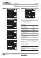
Coil versions, monostable
Coil Rated Operate Limiting Release Coil Rated coil
code voltage voltage Voltage voltage resistance power
VDC VDC
min.
VDC
max.
VDC
min.
Ω±10% mW
High sensitive version, 150mW
00 3 2.1 8.1 0.3 60 150
07 3.3 2.3 8.8 0.33 72 150
06 4.5 3.2 12.2 0.45 136 150
01 5 3.6 13.5 0.5 168 150
27 6 4.3 16.2 0.6 240 150
05 9 6.4 24.3 0.9 544 150
02 12 8.6 32.4 1.2 968 150
03 24 17.1 64.8 2.4 3872 150
04 48 34.1 129.6 4.8 15468 150
Sensitive version, 200mW
14 3 2 7 0.3 45 200
15 4.5 2.9 10.5 0.45 101 200
16 5 3.3 11.6 0.5 125 200
28 6 3.9 14 0.6 180 200
17 9 5.9 21 0.9 405 200
18 12 7.8 28 1.2 720 200
19 24 15.6 59.9 2.4 2880 200
20 48 31.2 112 4.8 11520 200
Sensitive version, 300mW
33 4.5 3.1 8.9 0.45 73 300
34 5 3.4 9.9 0.5 90 300
12 12 8.25 23.6 1.2 515 300
35 24 16.5 47.3 2.4 2060 300
36 48 32.5 54.6 4.8 8240 300
Standard version, 400mW
21 4.5 2.9 8.9 0.45 50 400
22 5 3.3 9.9 0.5 63 400
29 6 3.9 11.8 0.6 90 400
23 9 5.9 17.7 0.9 203 400
24 12 7.8 23.6 1.2 360 400
25 24 15.6 47.3 2.4 1440 400
26 48 31.2 94.6 4.8 5760 400
Standard version, 550mW
38 4.5 2.9 6.3 0.45 36 550
50 5 3.3 7 0.5 45 550
37 6 3.9 8.4 0.6 66 550
32 12 7.8 16.8 1.2 280 550
31 24 15.6 33.6 2.4 1050 550
30 48 31.2 67.2 4.8 4100 550
All figures are given for coil without pre-energization, at ambient temperature +23°C.
Other coil voltages on request.
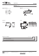
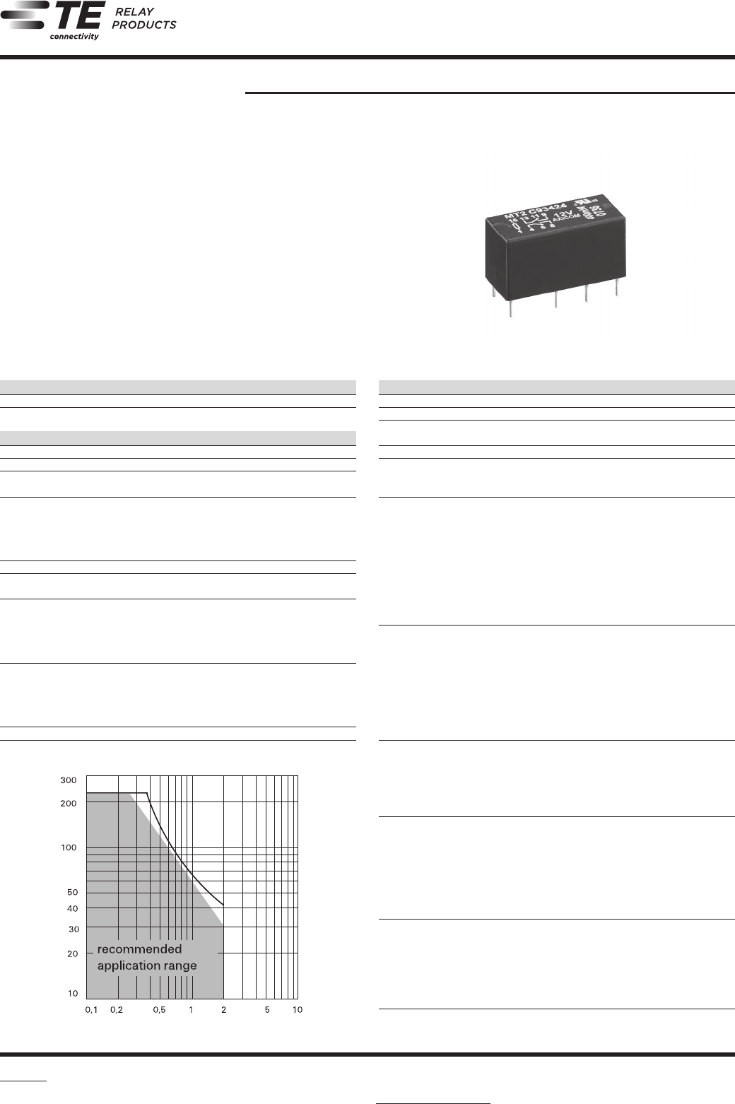
MT2 Relay
DC current [A]
DC voltage [VDC]
Max. DC load breaking capacity
Z