
Datasheet


108-98002 Rev. E
All specications subject to change. Consult Tyco Electronics for latest specications. 4 of 15
Telecom-, Signal and RF Relays
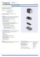
P2 V23079 Relay
AXICOM
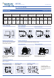
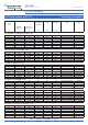
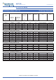
Dimensions Dimensions in mm
THT Version
Mounting hole layout
View onto the component side
of the PCB (top view)
Terminal assignment
Relay – top view
Non-latching type
not energized condition
Latching type,
reset condition
Latching, 2 coils
reset condition
Contacts in reset
position. Both coils can
be used either as set or
reset coils.
THT
V23079-x1xxx-B301
standard coil
THT
V23079-x2xxx-B301
overmolded coil
SMT long terminals
V23079-x1xxx-B301
standard coil
SMT long terminals
V23079-x2xxx-B301
overmolded coil
SMT short terminals
V23079-x1xxx-B301
standard coil
SMT short terminals
V23079-x2xxx-B301
overmolded coil
mm inch mm inch mm inch mm inch mm inch mm inch
L
W
H
14.5 ± 0.10
7.2 ± 0.10
9.8 ± 0.10
0.570 ± 0.004
0.283 ± 0.004
0.385 ± 0.004
14.6 ± 0.10
7.2 ± 0.10
9.5 ± 0.10
0.575 ± 0.004
0.283 ± 0.004
0.374 ± 0.004
14.5 ± 0.10
7.2 ± 0.10
10.4 ± 0.15
0.570 ± 0.004
0.283 ± 0.004
0.409 ± 0.006
14.6 ± 0.10
7.2 ± 0.10
9.9 ± 0.10
0.575 ± 0.004
0.283 ± 0.004
0.390 ± 0.004
14.5 ± 0.10
7.2 ± 0.10
10.4 ± 0.15
0.570 ± 0.004
0.283 ± 0.004
0.409 ± 0.006
14.6 ± 0.10
7.2 ± 0.10
9.9 ± 0.10
0.575 ± 0.004
0.283 ± 0.004
0.390 ± 0.004
T
T1
T2
Tw
S
3.25 – 0.25
N/A
N/A
0.5 ± 0.05
0.55 – 0.15
0.128 – 0.010
N/A
N/A
0.020 ± 0.002
0.022 – 0.006
3.25 – 0.25
N/A
N/A
0.5 ± 0.05
0.45
0.128 – 0.010
N/A
N/A
0.020 ± 0.002
0.018 ± 0.002
N/A
5.52 ± 0.15
9.4 ± 0.15
0.5 ± 0.05
N/A
N/A
0.217 ± 0.006
0.370 ± 0.006
0.020 ± 0.002
N/A
N/A
5.52
9.4 ± 0.15
0.5 ± 0.05
N/A
N/A
0.217 ± 0.006
0.370 ± 0.006
0.020 ± 0.002
N/A
N/A
5.52
7.4 ± 0.15
0.5 ± 0.05
N/A
N/A
0.217 ± 0.006
0.291 ± 0.006
0.020 ± 0.002
N/A
N/A
5.52
7.4 ± 0.15
0.5 ± 0.05
N/A
N/A
0.217 ±0.006
0.291 ±0.006
0.020 ±0.002
N/A
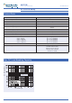
SMT Version
�
�
P2 SMT S
Long terminals Short terminals
0,9 ±0,1
Note: Solder pad for pin 6 and 7
only for latching with 2 coils
Note: Solder pad for pin 6 and 7
only for latching with 2 coils
Solder pad layout
View onto the component side of the PCB (top view)
Long terminals Short terminals
Note: Hole for pin 6 and 7 only
for latching with 2 coils. Basic
grid 2.54 mm