
Datasheet

108-98009 Rev. F
All specications subject to change. Consult Tyco Electronics for latest specications. 4 of 12
Telecom-, Signal and RF Relays
P1 V23026 Relay
AXICOM
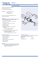
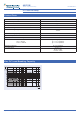
Dimensions Dimensions in mm
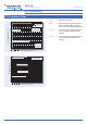
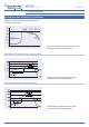
THT Version
Mounting hole layout
View onto the component side of the PCB
(top view)
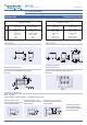
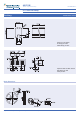
Terminal assignment
Relay – top view
Contact release or reset condition, coil polarity to set the relay
Non-latching type
not energized condition
Latching type, 1 coil
reset condition
Latching type, 2 coils
reset condition
Contacts are shown in
reset condition. Both
coils can be used either
as set or reset coil.
THT
V23026-x1xxx-B201
SMT
V23026-x1xxx-B201
mm inch mm inch
L
W
H
13.00 ± 0.10
7.60 ± 0.10
6.90 – 0.20
0.512 ± 0.004
0.299 ± 0.004
0.272 – 0.008
13.40 ± 0.10
7.75 ± 0.10
8.00 – 0.20
0.528 ± 0.004
0.305 ± 0.004
0.315 – 0.008
T
T1
T2
S
S1
S2
3.50 – 0.20
N/A
5.08 ± 0.15
0.30 ± 0.10
N/A
N/A
0.138 – 0.008
N/A
0.200 ± 0.006
0.012 ± 0.004
N/A
N/A
N/A
10.90 – 0.50
5.08 ± 0.15
N/A
0.85 ± 0.10
0.20 – 0.15
N/A
0.429 – 0.020
0.200 ± 0.006
N/A
0.033 ± 0.004
0.008 – 0.006
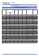
SMT Version
Solder pad layout
View onto the component side of the PCB
(top view)
Coplanarity ≤ 0.1mm