
User Manual
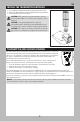

EN
2
TABLE OF CONTENTS
SPECIFICATIONS
Specifi cations ...................................................................... 2
Features and Descriptions .................................................. 2
Transmitter Layout .............................................................. 3
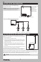
Receiver Layout and Connections ....................................... 4
Receiver Mounting and Antenna Installation ..................... 4
Install the Transmitter Batteries ......................................... 5
Transmitter and Receiver Binding ....................................... 5
Steering Trim (CH1) ............................................................. 6
Throttle Control Switch ....................................................... 6
Steering Dual Rates (D/R-CH1) ........................................... 6
Limited Warranty ................................................................ 6
Warranty and Service Contact Information ........................ 7
FCC Information................................................................... 8
IC Information...................................................................... 8
Compliance Information for the European Union ............... 8
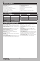
TRANSMITTER
Model AXI31618
Power Output <100mW
Voltage 4.8–6V
Power Supply 4 Cell Alkaline/Ni-Cd/Ni-MH
Frequency 2.4GHz FHSS
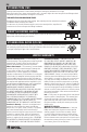
RECEIVER
Model AXI31620
Frequency 2.4GHz FHSS
Voltage 6–7.4V
Dimensions (mm) 33 x 33 x 15
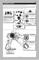
FEATURES AND DESCRIPTIONS
Receiver Antenna Wire: The antenna wire receives the
transmitter signal. The antenna wire should be installed
through a nylon tube (antenna tube) in the vertical position
for the best reception.
Auxiliary Channel 3 Switch: Switch to control servo.
Battery Compartment: Houses the 4 AA alkaline
batteries that power the transmitter.
Bind Button: Used in the process of binding the
transmitter and receiver.
Bind LED: Displays the current status of the transmitter
and receiver pair.
Steering Dual Rate (D/R): The Dual Rate keys are used to
adjust the Steering Dual Rate quickly and easily during use.
Grip: The grip is molded in an ergonomic shape for
increased comfort, control, and feel.
Power Indicator: Indicates that there is power to the
transmitter.
Power Switch: Turns the transmitter ON and OFF.
Steering Trim Knob (CH1): Used to adjust the center
TRIM of the steering servo.
Steering Wheel (CH1): Proportionally operates the model’s
right and left steering control. The steering wheel features a
molded grip for increased comfort, control, and feel.
Throttle Trigger (CH2): Controls the speed of the model,
both forward and backward, or the model’s brake.