
1/6 SCX6 Trail Honcho 4WD Manual


11
EN
1. Running Mode: Select your running mode, Forward and Reverse
without brake (F/R) is the preferred rock crawler mode. Select For-
ward Reverse and Brake (F/R/B) if you want to use reverse throttle
input to control brakes.
2. Cutoff Voltage: Low Voltage Cutoff (LVC) for Lipo Protection.
This item is mainly for preventing LiPo packs from being over-
discharged. If the LVC is enabled, the ESC will reduce the output to
50% and cut power 10 seconds later when the voltage goes below
the cutoff threshold. The red LED will begin a repeating single flash
when the ESC enters LVC.
If the LVC is disabled, the ESC will not cut off the power when the
voltage is low. We don’t recommend setting the LVC to “Disabled”
when using a LiPo pack, Without LVC it is easy for a LiPo battery to
be damaged due to over-discharge.
• NIMH - For a NiMH pack, we recommend setting this item to
“Disabled.”
• Cutoff Voltage - The ESC will set the cutoff for the pack based on
the voltage the battery is at when the battery is connected.
3. RPM / Throttle Matching: The motor RPM will change when the
vehicle encounters obstacles or terrain changes (RPM is based on
the loads on the vehicle). This setting manages how aggressively
the ESC will change the RPM under load.
When the throttle input remains unchanged, setting this item to
“Low” provides the feeling of a brushed motor. Setting it to “High”
provides a strong sense of speed-governing, making the vehicle
maintain speed at a given throttle setting regardless of the resis-
tance.
The default setting is medium. This feature is only available in
“Forward and Reverse (rock crawler)” mode.
4. Max. Forward Force: The power applied to the motor when the
throttle trigger is at the full throttle position. You can reduce the
value for better driving feel/control when you drive a crawler over
difficult terrain.
5. Max. Reverse Force: The power applied to the motor when the
throttle trigger is at the full reverse position. We recommend using
a low value for most drivers.
6. Turbo Timing: This item is adjustable from 0 degree to 10 degrees,
the value you select will initiate at full throttle. It’s usually activated
on long straightaways and makes the motor unleash its maximum
potential. Turbo timing adds a margin of power at full throttle.
7. Turbo Delay: When “Turbo Delay” is set to “Instant”, the Turbo
Timing will be activated immediately when the throttle trigger is
moved to the full throttle position. Turbo Delay values will delay the
application of the selected Turbo Timing value.
8. Drag Brake Force: Braking power when the throttle is at the neutral
position. Higher drag brake values are used to provide a stronger
hold or hill brakes.
IMPORTANT: Drag brakes will consume more power and heat will
be increased, start with small values and use with caution. Improve
ventilation to ESC if heat is excessive.
9. Drag Brake Rate: This feature manages how rapidly the ESC ap-
plies drag brakes. Choose the drag brake rate from level 1 (very
soft) to level 9 (very aggressive); lower values ramp the brakes
slower and prevent sudden stops or jerky stopping movements.
In Auto mode, the ESC adjusts the Drag Brake Rate automatically
based on the current speed and can be helpful to prevent the
vehicle from flipping over or from sustaining drivetrain damage
from harsh braking, but also provides a sensitive braking feel at low
speeds:
• The higher the current speed, the lower the drag brake rate.
• The lower the current speed, the higher the drag brake rate.
10. Neutral Range: Adjust this parameter to your preference to ac-
count for deadband in the throttle response. If you notice inconsis-
tent drag brakes, increase your Neutral Range value.
11. Start Mode/(Punch): Set the punch from level 1 (very soft) to level
9 (very aggressive). This feature is very useful for preventing tires
from spinning. Punch levels 7 and above require high discharge
capable batteries. If the car stutters or suddenly loses power when
accelerating it may indicate the battery does not have adequate
discharge capabilities for the application. Reduce the punch value,
pinion gear size, or change to a higher C rated battery.
12. BEC Voltage: Option 1: 6.0V Appropriate for most standard servos.
Not recommended for High Voltage (HV) servos.
• Option 2: 7.4V Appropriate for high voltage servos. Do not use this
option with standard servos; it’s possible a standard 5 – 6 Volt
rated servo will be damaged at this voltage setting.
13. Motor Rotation: Change this setting to reverse the motor rotation.
Do not change wiring order with this motor/ESC combo.
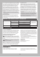
TROUBLESHOOTING
PROBLEM POSSIBLE CAUSE SOLUTION
The system will not connect
Your transmitter and receiver are too
close together
Move transmitter 8 to 12 feet away from receiver
You are near metal objects Move to an area with less metal
The receiver is bound to a different
model memory
Make sure the correct model memory is active in your
transmitter
Your transmitter was placed into bind
mode and is no longer bound to your
receiver
Rebind your transmitter and receiver, and then re-calibrate
The receiver goes into failsafe a short
distance away from the transmitter
Check for damage on the receiver
antenna
Make sure your receiver antenna is protected and located
as high as practical
Replace the receiver or contact Horizon Product Support
The receiver stops responding during
operation
Low receiver battery voltage. If the
battery voltage is low, it may drop
below 3.5V momentarily, causing the
receiver to brown-out, then reconnect
Charge the receiver or vehicle battery. Spektrum receivers
require at least 3.5V to operate
Loose or damaged wires or connectors
between battery and receiver
Check the wires and connection between the battery and
receiver. Repair or replace wires and/or connectors
Vehicle does not move
Batteries are not installed properly in
the transmitter
Ensure the transmitter batteries are properly installed
Weak or no battery in the vehicle Install a freshly charged vehicle battery
Damaged motor Replace the motor
Frayed or broken wiring Replace any damaged wiring
ESC is shut down by heat protection circuit
Allow the ESC to cool down completely
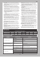
GEAR RATIOS
SPUR/PINION GEAR RATIO CHART
Pinion Size 11 12 13 14 15 16 17
Low Speed 81.47 74.68 68.94 64.01 59.75 56.01 52.72
High Speed 44.85 41.11 37.95 35.24 32.89 30.83 29.02
Standard Pinion