
User`s guide

4: Setup and Conguration • 21
©2014 Axia Audio - Rev.1.3.8
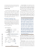
If the desire is to only mute the speaker and not trig-
ger the Busy indication, then wiring to pin 1 as opposed
to pin 2 would accomplish this.
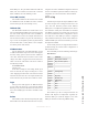
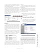
If using an Axia console, the Control Room (CR)
monitor logic has active logic when the monitors are
muted. This logic can be tied into the intercom station if
the main GPIO port is congured to the same LW Chan-
nel logic as dened in the show prole of the Axia con-
sole. Figure 4-12 shows the busy signal is active when
the monitors are muted.
Figure 4-11
Indicators
Intercom stations provide indicators on the Main
GPIO port which can be routed to a hardware GPIO port
for triggering of external devices. Pathnder can be used
to monitor the Main GPIO port of these state changes
and events can be trigger without the use of hardware
GPIO ports.
The indicators, also referred to as lamps, are placed
as GPI logic in the Main GPIO port so that GPIO routing
will resolve as a GPO on hardware ports. Pathnder is
able to monitor both GPI and GPO state changes.
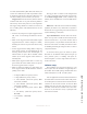
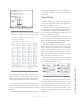
PIN FUNCTION
GPI Pin1 Listening Lamp
GPI Pin2
GPI Pin3 Ring Lamp
GPI Pin4 Mic Mute Lamp
GPI Pin5 Talking Lamp
Listening Lamp (GPI Pin 1) is engaged any time
the station is listening to a source. This can either be in
cases where the station is monitoring a source or when
another station is talking to the station, as this is also a
Listen state.
Ring Lamp (GPI Pin 3) is engaged when a lower trig-
gered station calls. When the call is accepted, the ring
lamp will release.
Mic Mute Lamp (GPI pin 4) is engaged when the
Mic mute button on the front panel is pressed, engaging
the Mic mute state. Pressing the button again releases
the Lamp and the mute state.
Talk Lamp (GPI pin 5) is engaged when the station
is talking to another station or also when another
station is listening.
Intercom Station Web Pages
The following section covers the HTML user
interfaces available. Some of the information
may be a repeat of items mentioned earlier.
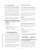
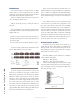
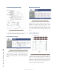
Home Page
Figure 4-12
The home page provides links to other conguration
pages as well as provide software version, uptime, and
internal temperature. The left hand side of the page is
consistent with other pages as a menu with all the need-
ed links too. When accessing the device for the rst time,
an authentication window comes up where the default
username is user and there is no password. The home
page will be presented after entering in the username/
password.