
User`s guide


Connecting GPIO • 34
Version 1.2 July 2010
type of source associated with it.
Assigning GPIO
A lot of the work of assigning logic to a source is
already done for you; once a GPIO port is linked with a
Source, all that remains to do is to connect the GPIO’s
DB-15 connectors to the device’s control interface.
A physical GPIO port may be associated with:
• a Livewire audio source
• another physical GPIO port (also known as a
GPIO snake)
• a virtual GPIO port (as in the case of the IP
Audio driver or IP-Intercom)
GPIO and Livewire Audio Sources
In the case if the IP-Intercom systems, you will not
typically use this method but it will be described here in
order to be complete.
So, how do you link a GPIO port with a Livewire
Source? It’s very easy; let’s do it step-by-step. We will
illustrate using the Element console’s web GUI.
1. Open your Web browser and enter the IP address
of your Element console or, if so equipped, your
PowerStation. Choose GPIO Conguration from
menu. Enter your password if prompted (default log-
in is “user”, leave the password field blank).
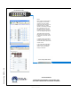
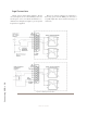
Note: If your systems includes a PowerStation,
you will have four GPIO ports. If your system
uses an Element Power Supply/GPIO unit, you
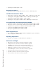
have eight GPIO ports as shown in Figure 4-1.
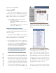
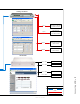
2. If you haven’t previously assigned any GPIO ports,
the GPIO definitions screen will be blank. Notice the
status indicators at the top of the page, showing the
state of the input and output pins of each port. Click
on the list icon to the right of an unused line. When
you click on any list icon, a small popup window will
open, enumerating all of the audio sources available
on the Livewire network (Figure B-2). Choose the
source you wish to associate with a GPIO port by
clicking on it; the window will close and the source’s
name and channel number will appear in the Chan-
nel box.
Figure B-2: GPIO Select Source popup list
3. Type a descriptive name in the Name field, and click
on the Save button at the bottom of the page.
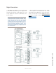
4. Look at the output status indicator for Port 1.
You’ll see that one of the pin status indicators is
lit in green; this means that the port is now send-
ing a GPIO logic state of “true” through this
pin. Assign the source for which you just creat-
ed a GPIO link to a Element channel; operate the
On and Off keys for the channel and watch the
pin status indicators change as you do so.
The source we’ve been using for this demonstration
is a telephone hybrid; we can now observe the pin
Figure B-1: GPIO denitions page