IP-Intercom System Installation & User’s Guide Manual Version 1.2.1 Aug 2010 IP-Intercom Software 1.2.
IMPORTANT NOTE: Axia Livewire devices are intended for use with an Ethernet Switch that supports multicast and QoS (Quality of Service). On a non-switched Ethernet hub, or a switch that is not enabled for multicast, this will result in network congestion that could disrupt other network activity. Important Safety Information To reduce the risk of electrical shock, do not expose this product to rain or moisture. Keep liquids away from the ventilation openings in the top and rear of the unit.
Customer Service We support you... By Phone/Fax in the USA. • Customer service is available from 9:30 AM to 6:00 PM USA Eastern Time, Monday through Friday at +1 216.241.7225. Fax: +1 216.241.4103. The 24-hour Telos/Omnia/Axia support line is +1 216.622.0247. By E-Mail. • The address is Support@AxiaAudio.com. Via World Wide Web. • The Axia Web site has a variety of information which may be useful for product selection and support. The URL is http://www.AxiaAudio.com.
Notice About This Manual All versions, claims of compatibility, trademarks, etc. of hardware and software products not made by Axia mentioned in this manual or accompanying material are informational only. Axia makes no endorsement of any particular product for any purpose, nor claims any responsibility for operation or accuracy. Warranty This product is covered by a five year limited warranty, the full text of which is included in the rear section of this manual.
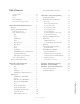
Table of Contents Console-Mounted Intercom Stations . . . . . . . . . 10 Customer Service . . . . . . . . . . . . . . . . . iii Warranty . . . . . . . . . . . . . . . . . . . . . . iv Chapter Three: Advanced Programming . . . . . . . . 13 Service . . . . . . . . . . . . . . . . . . . . . . . iv Assigning an IP Address . . . . . . . . . . . . . . . 13 About This Manual . . . . . . . . . . . . . . . . . iv IC.
Microphone opens. Speech, in tones soft and mellow. Introduction • vi A new broadcast day. Version 1.2.
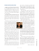
20 years ago, I designed my first broadcast console for PR&E. I look back on that time with great fondness; we were building bullet-proof boards for the world’s most prestigious broadcasters, making each new console design bigger and fancier to accommodate a wider variety of source equipment and programming styles. The console was the core of the studio; all other equipment was on the periphery. Then things changed: the PC found its way into broadcast audio delivery and production.
Who is so attuned that he may perceive the sound Introduction • viii of one bit dropping? Version 1.2.
Chapter One: Axia’s IP-Intercom products may operate as a standalone intercom system. The IP-Intercom system also integrates seamlessly with console and routing functions of any existing Axia Livewire network. Broadcasters have already discovered the advantages of using Axia networks. Less cost, less wiring and less setup time are just a few of the benefits gained from using Ethernet for real-time audio routing. Now, broadcast intercom systems benefit from those same advantages.
IP-Intercom Stations: Front Panel The rackmounted Livewire IP-Intercom stations incorporate a number of front panel connectors, controls and indicators to allow the operator to operate the system quickly and confidently. Front and rear panel views are shown for the 20-station OLED display and the 10-station film-cap user-legendable stations. The Element console versions of these stations incorporate the same controls in slightly different physical layouts.
Mute Speaker Tapping the Mute Speaker button alternately enables and disables the audio from the local speaker. sheet software. Create the 1/2 inch square labels for these buttons. Use your fingers to pop off the button cap and insert your label behind the clear button cap. Select The Select control is used to scroll through various menu options and to and select from pending calls. See the section that follows on the CALLSTACK channel.
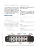
IP-Intercom Stations: Rear Panel All rackmounted intercom stations have identical rear panel configurations with the exception of the 10-station intercom expander. This expansion unit has only a Livewire jack, ID button and AC connector. The rear panel of the 20-station panel is illustrated in Figure 1-4 and described in the following section. Livewire (100 Base-T) Connector This connector is for connection to an approved Ethernet switch. It has two integral LEDs.
Figure 1-4: IC.20 - Rear Panel Callouts Analog Line Input Characteristics • Level: +4 dBu nominal (+24 dBu clip point) • Impedance : >/= 10 K Ohm balanced.
Featureless paper this page would have been empty 1: Introducing IP-Intercom • 6 save for this haiku. Version 1.
Setup and Operation Chapter 1: Introducing Axia IP-Intercom described the physical connections to the IP-Intercom stations. This chapter will discuss the operation of the IP-Intercom stations when used as a standalone system or in conjunction with your Element console and Livewire audio nodes. Please be sure to read Chapter 3: Advanced Programming so you will understand how you assign the IP address and Livewire channel numbers to your IP-Intercom station.
Figure 2-1: IC.20 Front Panel Controls 2: Basic Setup and Operation • 8 Select control and Assign/Enter key. Those controls are fully described in subsequent sections. Volume The rotary Volume control performs three functions. • It is used to adjust the overall level of the loudspeaker audio by simply rotating the control.
• • these menus. The Select control can also scroll and select incoming calls from stations not assigned to a local channel. See the section that follows on the CALLSTACK channel. Pressing the Select control will toggle between the main and alternate Channel Labels. This switches all labels on keys and menus. If an alternate label is not available, the main label will remain on the display The Select control is used in combination with the Assign/Enter key to navigate menus.
Figure 2-4: IC.1 Front Panel Controls 2: Basic Setup and Operation • 10 • In all menus, selecting Back will take you back to the Home Page. CALLSTACK (20-Station Panel) This CALLSTACK channel (found only on the 20-station rackmount panel and the 20-station Element console module) is used for monitoring and calling stations that are not assigned to a specific Talk/Listen channel on the user’s panel. The OLED lists up to four ringing, active and last completed calls.
fader, press the Enter key. The Intercom module will now be available. Figure 2-5: 10-Station Film-Cap Element Intercom Module Operation is nearly identical to rackmounted units with the difference being Element integration details. The audio source for the console modules is the Talkback audio of the Element (generated by the CR Microphone). The CR Headphone and Preview speaker are used instead of the headphone and speaker that is built into the rackmount panels.
In our youth we never dreamed that, one day, streams 2: Basic Setup and Operation • 12 might not have water. Version 1.
Chapter Three: Advanced Programming This chapter will walk you through the use of the IP-Intercom panel’s built in web pages to configure advanced features quickly, easily — and remotely! Assigning an IP Address When you first press the ID button, you will see the existing IP address of the unit. If it is “factory fresh”, you will see the display as shown in Figure 3-2. These four OLEDs display the four octets of the unit’s IP address. The factory default is 0.0.0.0.
IC.20 and IC.1 Intercom Web Pages All of the intercom panel’s parameters may be configured using the IP-Intercom Panel’s Web configuration pages. To access the Web pages from a computer, the computer and IP-Intercom Panel must be connected to the same LAN (or, the computer and Node can be connected using a “crossover 10/100 Base-T” Ethernet cable). To connect, open your web browser and enter the IP address of the device to be configured.
a unique number. As described in the Introduction to Livewire: IP-Audio System Design Reference and Primer, each Livewire stream must be assigned a unique channel number. You will want to develop a logical naming plan for your facility. For example you may wish to include the studio or rack name as part of your names to make life simpler when identifying sources in the future. We give some examples in the Introduction to Livewire manual.
4. Default (Dim lower priority sources; Mute IFB) 5. Above Normal (Dim lower priority, Mute Low Priority and IFB) 6. Above Normal (Dim low priority, Mute Low Priority and IFB) 7. High (Mute lower priority sources) 8. Highest (Mute lower priority sources) Dimming and muting of external sources is configured on the Ext Sources page (described in the next section). Dim Level This setting specifies the degree of dimming. It is variable from 0 (no dimming) to full mute.
the Talk pin for Marc. Listen Pin A contact closure to this pin will replicate pressing the front panel Listen key associated with this source. In Figure 3-6, Milos has pin 2 defined as his Listen pin and Marc has pin 5. NEW Additional Livewire sources can be added to the list of external sources by entering the relevant information in this row and then clicking the Apply button. Delete Checking the Delete box and clicking Apply will delete all checked sources from this intercom station.
Figure 3-8: IC.1 - Key Assign specify front panel film-cap button functions. Key Settings Each key has a drop-down to select the source assigned to that key. You may select only from valid IPIntercom sources or External sources that have been created on the previous configuration page. Figure 3-7: IC.20 - Key Assign Configuration 3: Advanced Programming • 18 tions are: • • • • Each key is also assigned a mode to determine the functions of the front panel switches.
tions are built into your IP-Intercom system. When you have interconnections to other equipment, you may need to extend the IP-Intercom logic functions to and from these non-Livewire devices. GPIO (General Purpose Input Output) can be a complicated topic. In an IP-Intercom system, GPIO is primarily used for the logic functions associated with Talk and Listen when we are communicating with other systems.
mode. Of course, since our communication path is fullduplex, we can Talk and Listen simultaneously so there is no limitation imposed. This web page can be used to monitor GPIO activity in real time so it is extremely useful for troubleshooting GPIO logic. You must have Java installed before your web browser can display the GPIO status boxes. They will illuminate green when active. GPIO Ports 1 and 2 are special. Port 1 is a hardware port and can be assigned to any Livewire GPIO function.
one system to another; some computers can provide very low timing irregularities and allow the receive buffer to be reduced to achieve lower audio delay. Default setting is 100 ms. 801.1p Tagging, 802.1p VLAN ID, 802.1q Priority, & DSCP Class of Service 802.1p tagging is necessary within the Livewire network to mark high-priority audio packets. This information is used by the Ethernet switches in the packet scheduling and queuing mechanism.
information. Our defaults are compatible with most Ethernet equipment defaults for the Class of Service that Livewire requires; you should not need to change them unless instructed by Axia Support. System Configuration Page The System Configuration page, shown in Figure 3-10, allows configuring the device’s IP address and related settings. It also permits choosing between a primary and secondary bank of software and to download new software into the secondary bank.
User Password This is the password required to connect to the unit. It must be at least 5 characters long and may be as long as 8 characters. Only alphanumeric characters are permitted. To change the password you must enter and verify the new password and then click Apply. NOTE: If you have changed the Firmware version the unit will reboot. If you have entered a new IP address or password the unit will not reboot.
Factory Reset (OLED panels only) If it is necessary to reset the unit to factory defaults for any reason, this can be accomplished by powering up the unit while the rear-panel ID button is depressed. Once the unit boots up, you will be prompted “Reset in 10 seconds” and if you continue to press the ID switch, the unit will reset to factory defaults and reboot. After the reboot, you will then be prompted to enter the IP address and subnet mask.
The configuration and operation of the IC.10X is quite straight-forward and if you have understood our previous section on the IC.20, you will have no problem extending that knowledge to the IC.10X. IP Address The IC.10X has an ID button on the rear panel. This switch is used in conjunction with Axia iProbe software or the BootP utility as described in detail at the beginning of this chapter. The IP address may also be changed from the System page of the configuration as shown in Figure 3-14.
dress since they are CANBus accessory panels that are associated with a specific Element console. The configuration of Element Intercom modules is very similar to the standalone intercom stations. The example shown in Figure 3-16 is for the 20-station Element module when used with a PowerStation.
cally. Also note that muting of the Preview speaker is handled automatically whenever any CR microphone is ON. Call Drop Flash This feature helps to inform you who has recently called. In a fast-paced environment, you will receive a quick messages from other Intercom users. The corresponding Listen indicator will continue to flash even after the caller has dropped the call.
you will configure: • The Intercom Source is selected from the dropdown menu. You may select from any connected IP-Intercom source or any external Livewire Sources that have been configured in the Intercom Livewire Sources section. • The channel Mode may be selected from the drop-down. This determines the actions of the film-cap buttons or Talk/Listen keys associated with the channel.
Please refer to Appendix B: Connecting GPIO for more details and a real world example. Intercom Livewire Sources IP-Intercom sources use an automatic source advertising scheme so no setup or external software is required. You may also wish to interface your IP-Intercom system to other non-Livewire equipment. You can accomplish this easily by using Axia audio nodes and GPIO nodes and configuring those sources in this section.
3: Advanced Programming • 30 Delete Checking the Delete box and clicking Apply will delete all checked sources from this intercom station. As expected, any keys with labels that may correspond to deleted stations will no longer function. Version 1.
Unbalanced Connections We’ve told you, both earlier in this manual, and in Introduction to Livewire; System Design Reference & Primer, that Axia recommends balanced audio connections when connecting analog source and destination gear to the inputs and outputs, respectively, of Axia nodes. Not only do we recommend this for the usual reasons, but because inter-channel crosstalk between the left and right channels of unbalanced signals sharing the same Cat. 5 cable is a possibility.
Alternatively, if both pieces of equipment are not both tied to a common facility ground, both sides of the shield must be connected. In this case the “-“ side of the nodes inputs are tied to the shield of the RJ-45 plug as follows: Axia node’s inputs fed from a floating source, with no + R + L 8 1 Unbalanced Connections • 32 facility ground in common with the Axia node. Version 1.
Connecting GPIO This Appendix will give you some basic information on GPIO (General Purpose Input Output) ports. Please refer to the manuals supplied with your Element or GPIO node for more details on integration with other non-intercom GPIO. GPIO Port Definitions Axia GPIO devices utilize DB-15 connectors on their back panels. Each connector (also known as a GPIO port) can be associated with the logic functions of a device in your studio.
type of source associated with it. Assigning GPIO A lot of the work of assigning logic to a source is already done for you; once a GPIO port is linked with a Source, all that remains to do is to connect the GPIO’s DB-15 connectors to the device’s control interface.
status indicators change as we turn the channel on and off, as shown in Figure B-3. The Engineering Room GPIO port 2 would look something like this: Figure B-3: Pin status indicators showing GPIO port activity GPIO Snake When you “connect” two GPIO ports together via their port configuration, we call that a GPIO snake. This may be useful to make GPIO logic travel over the network from one room to another.
Version 1.
Input Connections Connecting GPIO • 38 Current on these inputs must be limited to 20 mA or less, through the use of a current-limiting resistor. An external power source (24 volts DC maximum) is recommended for all inputs and outputs, to prevent ground loops between equipment. However, if customer equipment is completely isolated, using power from the GPIO port connectors is acceptable. Figure B-4 shows details for both types of connections: Figure B-4 GPIO input connections Version 1.
Output Connections The GPIO port’s outputs are opto-isolated. Current should be limited 100 mA through each output, with the total current draw from the +5 Volt supply not to exceed 3 amps. Figure B-5 shows the recommended connections for outputs: Please note that this section is provided as a “jumpstart” introduction to Axia GPIO nodes. For a fuller understanding of the GPIO node’s options and requirements, you may wish to read the GPIO Node User’s Manual that is available for download at www.AxiaAudio.
Connecting GPIO • 40 Version 1.
Appendix C: Specifications and Warranty Axia System Specifications Microphone Preamplifiers • • • • • Source Impedance: 150 ohms Input Impedance: 4 k ohms minimum, balanced Nominal Level Range: Adjustable, -75 dBu to -20 dBu Input Headroom: >20 dB above nominal input Output Level: +4 dBu, nominal Analog Line Inputs • • • Input Impedance: >40 k ohms, balanced Nominal Level Range: Selectable, +4 dBu or -10dBv Input Headroom: 20 dB above nominal input Analog Line Outputs • • • • Output Source Impedance:
• Digital Input to Digital Output: 138 dB Equivalent Input Noise • Microphone Preamp: -128 dBu, 150 ohm source, reference -50 dBu input level Total Harmonic Distortion + Noise • • • • Mic Pre Input to Analog Line Output: <0.005%, 1 kHz, -38 dBu input, +18 dBu output Analog Input to Analog Output: <0.008%, 1 kHz, +18 dBu input, +18 dBu output Digital Input to Digital Output: <0.0003%, 1 kHz, -20 dBFS Digital Input to Analog Output: <0.
Axia Limited Warranty This Warranty covers “the Products,” which are defined as the various audio equipment, parts, software and accessories manufactured, sold and/or distributed by TLS Corp., d/b/a Axia Audio (hereinafter “Axia Audio”). With the exception of software-only items, the Products are warranted to be free from defects in material and workmanship for a period of five (5) years from the date of receipt by the end-user.
Axia Audio, a Telos Company • 1241 Superior Ave. • Cleveland, Ohio, 44114, USA • +1.216.241.7225 • www.AxiaAudio.