Reverse Osmosis User’s Manual Model R1-1140, R1-2140, R1-3140, R1-4140, R1-5140, R1-6140 R1-6140 Pictured MKTF - 211 07/26/12
This Page Intentionally Left Blank 2 MKTF - 211 07/26/12
TABLE OF CONTENTS INTRODUCTION ................................................................................................................................... 4 SAFETY ................................................................................................................................................ 4 FEED WATER AND OPERATION SPECIFICATIONS .................................................................................. 5 REJECTION, RECOVERY AND FLOW RATES..................................
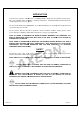
INTRODUCTION Your R1-Series system is a durable piece of equipment which, with proper care, will last for many years. This User’s Manual outlines installation, operation, operation, maintenance, and troubleshooting details vital to the sustained performance of your system. The test results which are included with this User’s Manual indicate your system’s permeate (product) and concentrate (waste) test results.
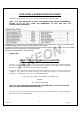
FEED WATER & OPERATION SPECIFICATIONS Nothing has a greater effect on a reverse osmosis system than the feed water quality. NOTE: IT IS VERY IMPORTANT TO MEET THE MINIMUM FEED WATER REQUIREMENTS. FAILURE TO DO SO WILL CAUSE THE MEMBRANES TO FOUL AND VOID THE MANUFACTURER’S WARRANTY. NOTE: HIGHER FEED TDS AND/OR LOWER TEMPERATURES WILL REDUCE THE SYSTEM’S PRODUCTION.
The amount of permeate water recovered for use is expressed as a percentage. To calculate % recovery, use the following formula: % Recovery = (Product Water Flow Rate / Feed Water Flow Rate) x 100 Example: 26% = (1.04/4.00) x 100 % Rejection = [(Feed TDS – Product TDS) / Feed TDS] x 100 Example: 99% = [(550-5.5)/550] x 100 NOTE: ALL FLOW RATES MUST BE EXPRESSED IN THE SAME UNITS.
CONCENTRATE (WASTE WATER) CONNECTION Locate the 1” or 3/4” connection (Depending on the unit) labeled concentrate and attach to a drain. Run the concentrate line to an open drain in a free and unrestricted manner (no backpressure). It is advised that an air-break break be used on the concentrate line to prevent siphoning of water from the pressure vessels when the system is in standby.
ALWAYS feed the pump with filtered water. The pump is susceptible to damage from sediment and debris. If any damage occurs to your system’s pump a re-build kit may be available. Contact your local dealer or distributor and inform them of your system’s model and pump size. MOUNTING The free standing system should be bolted down in compliance with local regulation standards or securely fastened.
HF5-OPTIONAL 9 MKTF - 211 07/26/12
NF3-OPTIONAL 10 MKTF - 211 07/26/12
NF4-OPTIONAL 11 MKTF - 211 07/26/12
LC LE-4040-OPTIONAL 12 MKTF - 211 07/26/12
MKTF - 211 07/26/12
LC HR-4040-OPTIONAL 14 MKTF - 211 07/26/12
MKTF - 211 07/26/12
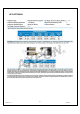
R1-1140, R1-2140, R1-3140, R1-4140, R1-5140, R1-6140 SYSTEM IDENTIFICATION FIGURE 1A 16 MKTF - 211 07/26/12
NUMBER IDENTIFICATION 1. SOLENOID VALVE – TURNS ON/OFF FEED WATER 2. 5 MICRON SEDIMENT – REMOVES PARTICULATES 3. PRESSURE GAUGE – MEASURES FEED PRESSURE 4. PRESSURE GAUGE – MEASURES PRESSURE AFTER FILTERS 5. PRESSURE GAUGE – MEASURES PUMP PRESSURE 6. PRESSURE GAUGE – MEASURES CONCENTRATE PRESSURE 7. COMPUTER CONTROL – CONTROLS RO SYSTEM FUNCTIONS 8. RECYCLE VALVE – RECYCLES CONCENTRATE BACK TO FEED (IF APPLICABLE) 9.
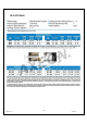
FIGURE 1B 18 MKTF - 211 07/26/12
FIGURE 1C FIGURE 1D 19 MKTF - 211 07/26/12
FIGURE 1E FIGURE 1F Note: A portion of the frame has been removed to expose components.
SYSTEM PURGING Carefully inspect your system before initial start-up. Check that all plumbing and electrical connections are not loose or have not come undone during shipment. A User’s Manual, Test Results, and Filter Housing Wrench will accompany your R1-Series reverse osmosis system. NOTE: LEAVE THE POWER TO THE SYSTEM OFF FOR THIS PROCEDURE. 1. Redirect permeate water to the drain for this procedure. 2. Fully open the concentrate valve (Counter Clockwise). (Figure 1B, Page. 16) 3.
FIGURE 2 INITIAL START-UP 1. Keep the permeate water line to drain for this procedure. 2. Fully open the concentrate valve (Counter Clockwise). (Figure 1B, Page. 16) 3. Fully close the recycle valve (Clockwise)(If Applicable). (Figure 1B, Page. 16) 4. Adjust the throttle valve at 50% open (Counter Clockwise). (Figure 1D, Page. 17) 5. Turn the RO system on and adjust the concentrate (waste) valve, recycle valve (If Applicable), and the throttle valve to the designed flow and pressure. (Figure 1B, Page.
DESIGN BASIS FOR R1-1140, R1-2140, R1-3140, R1-4140, R1-5140, R1-6140 Specifications WARNING: NEVER EXCEED THE SYSTEM’S MAXIMUM PRESSURE RATING 23 MKTF - 211 07/26/12
OPERATING DO’s AND DONT’S DO: Change the cartridge filters regularly Monitor the system and keep a daily log Run the system, as much as possible, on a continuous basis. Adjust the system recovery to the recommended value Always feed the pump with filtered water.
PERMEATE (PRODUCT) FLOW METER AND CONCENTRATE (WASTE) FLOW METER These flow meters indicate the flow rates of the permeate and concentrate water. The measurements, when added together, also indicate the feed water flow rate or (total flow rate) if the recycle valve is not being used. If the recycle valve is being used, add the flow rates for all three flow meters (permeate, concentrate, and recycle) to obtain the total feed flow.
MEMBRANE REMOVAL AND REPLACEMENT Replacing membranes in the pressure vessels is an easy process if you have the proper information and tools at hand. Please refer to the following instructions when removing and replacing membrane elements: WARNING: ALL PRESSURE GAUGES MUST READ ZERO BEFORE PROCEEDING. BEFORE ATTEMPTING, DISCONNECT THE POWER FROM THE SYSTEM AND BLEED ALL WATER PRESSURE FROM THE SYSTEM. 1. Remove the end plugs from the top of the pressure vessels.
6. Re-install install the end plugs by gently twisting the end cap while pushing it onto the housing. Ensure that you do not pinch or fatigue any O-rings O while re-installing installing the end plug. Push the end plug on until the outer diameter of the plug is flush with the outer diameter of the pressure vessel. 7. Insert the two half-moon moon retaining disks until they are fully seated. Subsequently fasten using a #5 Allen wrench. 8.
FLUSHING THE SYSTEM The system should be flushed weekly to remove sediment from the surface of the membranes. To manually flush the system, follow the preceding steps: 1. The system must be operating during the flush procedure. 2. Fully open the concentrate valve. (Figure 1B, Page. 16) 3. Allow the system to run for 10 to 20 minutes. 4. After 10 to 20 minutes, close the concentrate valve to its previous setting. Ensure the proper concentrate flow rate is going to the drain. 5.
REVERSE OSMOSIS TROUBLESHOOTING SYMPTOMS LOW INLET PRESSURE LOW PERMEATE FLOW HIGH PERMEATE FLOW POOR PERMEATE QUALITY POSSIBLE CAUSES CORRECTIVE ACTION Low supply pressure Increase Inlet Pressure Cartridge filters plugged Change Filters Solenoid valve malfunction Concentrate valve might be damaged Replace Sol.
ABNORMAL PERMEATE FLOW As time progresses, the efficiency of the membrane will be reduced. In general, the salt rejection does not change significantly until two or three years after installation when operated on properly pretreated feed water. The permeate flow rate will begin to decline slightly after one year of operation, but can be extended with diligent flushing and cleaning of the system. A high pH and/or precipitation of hardness can cause premature loss in rejection.
TEMPERATURE CORRECTION FACTORS FOR MEMBRANE Find the temperature correction factor (TCF) from the table below. Divide the rated permeate flow at 77°F by the temperature correction factor. The result is the permeate flow at the desired temperature.
If a system is rated to produce 5 gpm of permeate water @ 77˚ F. The same system will produce more water at a higher temperature. It will also produce less water at a lower temperature. Use the temperature correction table to obtain the correct flow. Example: 5 gpm @ 59˚ F (5÷1.42=3.52 gpm) 5 gpm @ 77˚ F (5÷1=5 gpm) 5 gpm @ 84˚ F (5÷0.89=5.62 gpm) SERVICE ASSISTANCE If service assistance is required, please complete the following process: Contact your local dealer or distributor.
OPERATION Company: ____________________ Date of StartUp: ___________________ ____________________ Date of Last Cleaning: ___________________ Location: Week Of: ____________________ System Serial #: ____________________ DATE TIME HOUR OF OPERATION FILTER INLET PRESSURE (PSI) FILTER OUTLET PRESSURE (PSI) CONCENTRATE PRESSURE (PSI) PUMP DISCHARGE PRESSURE (PSI) FEED FLOW (GPM) PERMEATE FLOW (GPM) CONCENTRATE FLOW (GPM) RECYCLE FLOW (GPM) RECOVERY % FEED TEMPERATURE FEED TDS (PPM) PERMEATE TDS (PPM)
DRAWINGS FIGURE 5A FIGURE 5B 34 MKTF - 211 07/26/12
FIGURE 6 35 MKTF - 211 07/26/12
FIGURE 7 36 MKTF - 211 07/26/12
Note: A portion of the frame has been removed to expose components.
R1-1140 SYSTEM PART LIST Item No. Quantity Part Number Description 1 1 200906 SWITCH, PRESSURE, LOW, N/O 15-30, ¼” FNPT 2 1 200795 PUMP, MULTI-STAGE, 1.5 HP, 110/220V, 1PH 10GBS1514Q4, GOULDS 3 1 205903 VALVE, GLOBE, SS, 1” FNPT 4 1 204914 VALVE, SOLENOID, N/C, UL, 220V, 1” FNPT 5 1 200640 CART, SEDIMENT, PLEATED, 4.5” x 20”, 5 MIC 6 1 203649 HOUSING, FILT, BLK/BLU, 4.
R1-2140 SYSTEM PART LIST Item No. Quantity Part Number Description 1 1 200906 SWITCH, PRESSURE, LOW, N/O 15-30, ¼” FNPT 2 1 200795 PUMP, MULTI-STAGE, 1.5 HP, 110/220V, 1PH 10GBS1514Q4, GOULDS 3 1 205903 VALVE, GLOBE, SS, 1” FNPT 4 1 204914 VALVE, SOLENOID, N/C, UL, 220V, 1” FNPT 5 1 200640 CART, SEDIMENT, PLEATED, 4.5” x 20”, 5 MIC 6 1 203649 HOUSING, FILT, BLK/BLU, 4.
R1-3140 SYSTEM PART LIST Item No. Quantity Part Number Description 1 1 200906 SWITCH, PRESSURE, LOW, N/O 15-30, ¼” FNPT 2 1 200795 PUMP, MULTI-STAGE, 1.5 HP, 110/220V, 1PH 10GBS1514Q4, GOULDS 3 1 205903 VALVE, GLOBE, SS, 1” FNPT 4 1 206688 VALVE, SOLENOID, 2-WAY,BRASS, 100–240V, 1” FNPT, ASCO 5 1 200640 CART, SEDIMENT, PLEATED, 4.5” x 20”, 5 MIC 6 1 203649 HOUSING, FILT, BLK/BLU, 4.
R1-4140 SYSTEM PART LIST Item No. Quantity Part Number Description 1 1 200906 SWITCH, PRESSURE, LOW, N/O 15-30, ¼” FNPT 2 1 200795 PUMP, MULTI-STAGE, 1.5 HP, 110/220V, 1PH 10GBS1514Q4, GOULDS 3 1 205903 VALVE, GLOBE, SS, 1” FNPT 4 1 206688 VALVE, SOLENOID, N/C, UL, 220V, 1” FNPT 5 1 200640 CART, SEDIMENT, PLEATED, 4.5” x 20”, 5 MIC 6 1 203649 HOUSING, FILT, BLK/BLU, 4.
R1-5140 SYSTEM PART LIST Item No. Quantity Part Number Description 1 1 200906 SWITCH, PRESSURE, LOW, N/O 15-30, ¼” FNPT 2 1 200795 PUMP, MULTI-STAGE, 1.5 HP, 110/220V, 1PH 10GBS1514Q4, GOULDS 3 1 205903 VALVE, GLOBE, SS, 1” FNPT 4 1 204914 VALVE, SOLENOID, N/C, UL, 220V, 1” FNPT 5 1 200640 CART, SEDIMENT, PLEATED, 4.5” x 20”, 5 MIC 6 1 203649 HOUSING, FILT, BLK/BLU, 4.
R1-6140 SYSTEM PART LIST Item No. Quantity Part Number Description 1 1 200906 SWITCH, PRESSURE, LOW, N/O 15-30, ¼” FNPT 2 1 206427 PUMP, MULTISTAGE,2HP,115/208230V,1PH,TEFC,18GBS2014N4 3 1 205903 VALVE, GLOBE, SS, 1” FNPT 4 1 204914 VALVE, SOLENOID, N/C, UL, 220V, 1” FNPT 5 1 200640 CART, SEDIMENT, PLEATED, 4.5” x 20”, 5 MIC 6 1 203649 HOUSING, FILT, BLK/BLU, 4.
R1-1140 FLOW DIAGRAM 44 MKTF - 211 07/26/12
R1-2140 FLOW DIAGRAM 45 MKTF - 211 07/26/12
R1-3140 FLOW DIAGRAM 46 MKTF - 211 07/26/12
R1-4140 FLOW DIAGRAM 47 MKTF - 211 07/26/12
R1-5140 FLOW DIAGRAM 48 MKTF - 211 07/26/12
R1-6140 FLOW DIAGRAM 49 MKTF - 211 07/26/12
MKTF - 211 07/26/12
MKTF - 211 07/26/12
MKTF - 211 07/26/12
MKTF - 211 07/26/12
MKTF - 211 07/26/12
MKTF - 211 07/26/12
MKTF - 211 07/26/12
MKTF - 211 07/26/12
This Page Intentionally Left Blank 58 MKTF - 211 07/26/12