
User guide


MKTF - 215
Feed and Dr
ain Connection
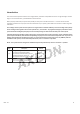
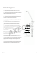
Feed Connection
1. Locate and turn off the angle stop v
al
will usually be locat
ed under the sink on the pipe
2. When the angle stop valv
e is closed,
tap on the sink.
3. Disconnect the cold water faucet f
eed line
4. Install the feed adapter int
o the angle
5. Firmly press the green 1/4” tubing i
nt
6. Connect the cold water faucet f
eed line i
7. Make sure the small shut-off valv
e on the g
connection valve. Check for leaks.
7. Attach the small feed valve warning
t
8. Attach the Shut-off Warning label t
o the
Date of Installation label and attach t
o the side of the
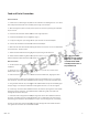
Drain Connection
1. Y
ou will need an electric drill with a 3/8” bit and a sc
installation.
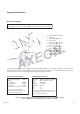
2. Obtain the drain saddle assembly, t
w
adhesive foam pad fr
om the small parts bag (Fig. 2).
3. Place the adhesive f
oam pad on the inside of the d
4. Position the drain saddle on the dr
ain pipe under the sink b
sink connection. Orient the dr
ain saddle so th
5. Using the bolts and hex nuts, hand
tig
the pipe snugly. Use a Phillips screwdri
v
6. If necessary, remove the dr
ain saddle
Using the connector opening in
the side of the d
through the wall of the drain pipe.
7.
Extend the drain tubing from the RO dispensing faucet to the drain saddle and measure
for length. The tubing must be routed so that water can run downhill for the entire length
of the tubing from the faucet. Avoid low spots or loops. Cut the tubing shorter
8. Insert the drain tube from the RO dispensing faucet through the drain saddle connector
nut. Tighten the connector nut onto the drain saddle.
ain Connection
al
ve on the cold water line feeding the sink. This valv
e
ed under the sink on the pipe
coming out of the wall.
e is closed,
relieve pressure in the line by opening the cold wat
er
eed line
at the angle stop valve.
o the angle
stop. (Fig. 1)
nt
o the 1/4" connector on the feed adapter.
eed line i
nto the feed adapter.
e on the g
reen feed line is closed. Turn on the feed wat
er
t
ag from the parts bag to the feed valve.
o the
system so that it is directly visible. Fill out the
o the side of the
system.
ou will need an electric drill with a 3/8” bit and a sc
rewdriver for this portion of the
w
o 1 ½” bolts, two 3/8” hex nuts, and the small
om the small parts bag (Fig. 2).
oam pad on the inside of the d
rain saddle front, aligning the holes.
ain pipe under the sink b
etween the “P” trap and the
ain saddle so th
at the opening is on the side of the drain pipe.
tig
hten the saddle bracket evenly until
the saddle grips
v
er to fully tighten the bolts. Do not over tighten.
ain saddle
connector nut from the opening of the dr
ain saddle.
the side of the d
rain saddle as a guide, drill a 3/8" hole
Extend the drain tubing from the RO dispensing faucet to the drain saddle and measure
for length. The tubing must be routed so that water can run downhill for the entire length
of the tubing from the faucet. Avoid low spots or loops. Cut the tubing shorter
, if necessary.
8. Insert the drain tube from the RO dispensing faucet through the drain saddle connector
nut. Tighten the connector nut onto the drain saddle.
7
e
er
er
the saddle grips
ain saddle.
Fig. 1
Note: The drain saddle
assembly must be installed
before the ‘P’ trap. Do not
install the drain saddle
assembly between the ‘P’
trap and the wall.
Fig. 2