CRO-Series 5-Stage Reverse Osmosis System Installation and Maintenance Manual MKTF - 215
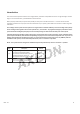
Please fill out the following information at the time of installation. Save for future reference. Model: Date Code: Install Date: Sold by: Installed By: Service Center Phone Number: .
Introduction This reverse osmosis systems features a four-stage prefilter, membrane and postfilter housed in a single cartridge. The fifth stage, an in-line carbon filter, is placed between tank and faucet. When properly maintained, this system will provide you with years of trouble-free service. The next sections contain important information on the proper care and maintenance of your system, please take a few minutes to read through this information.
Limited Warranty This Limited Warranty extends to the original purchaser of the system only. This warranty covers all Manufacturer-supplied items only that prove to be defective in material, workmanship or factory preparation. This warranty covers parts only; all labor is excluded from this warranty, including, but not limited to, services related to the removal, replacement, installation, adjustment, maintenance and/or repair of the unit or its components items.
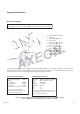
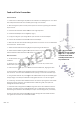
System Specifications Dimensions and Weight System - 9.72” W x 13.75” D x 15.38” H ( 24.7 x 34.9 x 39.1 cm), 11 lbs. (5 kg.) Shipping Box - 14.5"L x 11.25"W x 20"H (36.8 x 28.6 x 50.8 cm), 13.7 lbs. (6.2 kg.) D G E I L F M H K BB C (not shown) J) A. B. C. D. E. F. G. H. I. J. K. L. M.
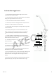
Push Handle Airgap Faucet 1. Locate the faucet parts bag and arrange the parts on the countertop in the sequence shown. 2. Locate the piece of white tubing. Pull the white, black and blue tubing up through the faucet hole in the sink. 3. Insert the rubber seal onto the base of the faucet. 4. Push the 1/4” black drain tubing attached to the system onto the smaller 1/4” barb located on the faucet base. 5. Push the 3/8” white tubing onto the larger 3/8” fitting located on the faucet base. 6.
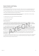
Feed and Drain ain Connection Feed Connection 1. Locate and turn off the angle stop val alve on the cold water line feeding the sink. This valvee will usually be located ed under the sink on the pipe coming out of the wall. 2. When the angle stop valvee is closed, relieve pressure in the line by opening the cold water er tap on the sink. 3. Disconnect the cold water faucet feed eed line at the angle stop valve. 4. Install the feed adapter into o the angle stop. (Fig. 1) 5.
System Activation and Flushing System Activation and Inspection 1. Check all tubing connections to ensure they are firmly seated. CHECK TO SEE THAT THE CARTRIDGE RETAINER CLIP IS PROPERLY ENGAGED AND LOCKED. Failure to keep the retaining clip in place will result in accidental leaks and flooding. 2. Open the dispensing faucet at the sink. Close the tank shut-off valve. Make sure the feed valve for the incoming water is open. Open the small feed shut-off valve on the green feed line. 3.
Installation Checklist 1. System is located where it will not be subject to physical impacts or rough contact by heavy objects. 2. Feed water pressure to the unit is no less than 40 psi and no greater than 80 PSI. 3. Ensure the plastic retainer clip that holds the membrane cartridge in place is fully engaged and locked in place. The slide locks must snap into place in the slots. If the clip does not snap easily into place through the slots it means the cartridge is not fully inserted into the connectors.
Maintenance Cartridge Replacement 1. Close the feed water shut-off valve. 2. Close the tank shut-off valve. 3. Open the dispensing faucet to relieve system pressure. Close dispensing faucet when flow has stopped. 4. Remove the cover from the front of the system. Remove the retaining clip. Pull the cartridge off the system evenly at top and bottom. Dispose of used cartridge. 6.