
User Manual


Axell Wireless Limited
Technical Literature
Lincoln/Holland Upgrade Equipment
Document Number
60
-
214701HBKM
Issue No.
1
Date
29/08/2008
Page
31
of
43
6. Installation – General Notes
6.1 General Remarks
When this equipment is initially commissioned, please use the equipment set-up record sheet in
Appendix B. This will help both the installation personnel and Axell Wireless should these figures be
needed for future reference or diagnosis.
The procedure for installing and commissioning an Axell Wall Mount Repeater is generally as follows:
1 Secure the Repeater in the chosen wall position.
2 Fix the antenna and connect its cables to the Repeater antenna ports.
3 Connect a suitable mains or battery power supply to the Repeater
4 Calculate the attenuation settings required for the uplink and the downlink paths, and set the
attenuators as described elsewhere in this document.
5 Switch the equipment mains on with the small switch located inside the Repeater on the lower
right hand side of the case.
6 If Base Station signals are available, make test calls via the Amplifier to ensure correct
operation, if possible monitoring the signal levels during these calls to ensure that the uplink
and downlink RF levels are as anticipated.
6.2 Electrical Connections
It is recommended that the electrical mains connection is made by a qualified electrician, who must be
satisfied that the supply will be the correct voltage and of sufficient capacity.
All electrical and RF connections should be completed and checked prior to power being applied for
the first time.
Ensure that connections are kept clean and are fully tightened.
6.3 RF Connections
Care must be taken to ensure that the correct connections are made with particular attention made to
the base station TX/RX ports. In the event that the base transmitter is connected to the RX output of
the equipment, damage to the equipment will be done if the base station transmitter is then keyed.
6.3.1. Termination of Unused Ports
In the event that any RF ports are unused (available for future expansion) these ports must be kept
terminated with the load terminations supplied by Axell for that purpose
Ensure that connections are kept clean and are fully tightened.
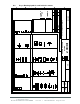
6.4 Optical Connections
The optical input and output ports will be shown in the system drawings. The ports are supplied with a
green plastic cover, which must be removed prior to the connection of the fibre cable. Ensure that
transmitter and receiver fibre cable are identified to prevent misconnection. At the master site, the
fibre transmitters are in the downlink path with the receivers in the uplink. At the remote sites the fibre
transmitters are in the uplink with the receivers in the downlink.
Always ensure that connections are kept clean and are fully tightened.