
Handbook
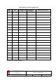

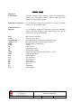


Table Of Contents
- AMENDMENT LIST RECORD SHEET
- INTRODUCTION
- 1.SAFETY CONSIDERATIONS
- 2.OVERVIEW/SYSTEM DESCRIPTION
- 3.SPECIFICATIONS
- 3.1Parts Lists
- 3.2Technical Specifications
- 3.2.1UHF ONE to Tunnels 1 & 2 Technical Specification
- 3.2.2UHF1A Technical Specification
- 3.2.3UHF ONE to Location TWO Technical Specification
- 3.2.4UHF TWO to Tunnels 1 & 2 Technical Specification
- 3.2.5UHF TWO to Location TWO Technical Specification
- 3.2.6800MHz Bi-directional Amplifier to Location TWO Technical Specification
- 3.3Mechanical Specification (UHF1/1A & UHF2 Wall Cases)
- 4.SYSTEM DRAWINGS
- 5.SUB-UNIT MODULES
- 5.1UHF 1 Air Interface (60-055901)
- 5.1.1Bandpass Duplexers (02-013401)
- 5.1.22 & 4 Way UHF Splitters (05-002603 & 05-003401)
- 5.1.3¼Watt 0- -30dB Switched Attenuator \(10-00
- 5.1.4Low Noise Amplifiers (11-006102, 11-007302 & 11-007402)
- 5.1.4.1General Description
- 5.1.4.2Technical Specification (11-006102)
- 5.1.4.3Drg. No. 11-006102, Low Noise Amplifier General Assembly
- 5.1.4.4Drg. No. 11-006170, LNA RF Circuit Diagram
- 5.1.4.5Drg. No. 11-006171, LNA DC Wiring Diagram
- 5.1.4.6Drg. No. 11-003971, LNA DC Schematic Diagram
- 5.1.4.7Technical Specification (11-007302)
- 5.1.4.8Drg. No. 11-007302, LNA Assembly With Alarm Relay
- 5.1.4.9Drg. No. 11-007370, LNA RF Circuit Diagram
- 5.1.4.10Drg. No. 11-007371, LNA DC Wiring Diagram
- 5.1.4.11Technical Specification (11-007402)
- 5.1.4.12Drg. No. 11-007402, LNA General Assembly
- 5.1.4.13Drg. No. 11-007470, LNA RF Circuit Diagram
- 5.1.4.14Drg. No. 11-007471 LNA DC Wiring Diagram
- 5.1.55Watt Power Amplifier (12-001801)
- 5.1.5.1Description
- 5.1.5.2Technical Specification
- 5.1.5.3Drg. No. 12-001801, 5Watt PA General Assembly Drawing
- 5.1.5.4Drg. No. 12-001870, 5Watt PA Circuit Diagram
- 5.1.5.5Drg. No. 12-001870C1, 5W PA Component List(1)
- 5.1.5.6Drg. No. 12-001870C2, 5W PA Component List(2)
- 5.1.5.7Drg. No. 80-008450, Power Amplifier/Alarm Board DC Wiring Details
- 5.1.63 Stage Amplifier Alarm Boards (12-002201)
- 5.1.7DC/DC Converter, 24V in, 12V 8A out (13-003011)
- 5.1.8Channel Selective & Channel Control Modules (17-003012 & 17-002101)
- 5.1.8.1Channel Selective Module Description
- 5.1.8.2Drg. No. 17-003080, Generic Channel Module Block Diagram
- 5.1.8.3Channel Selectivity Control Module Description
- 5.1.8.4Channel Controller DIP Switch Configuration Frequencies
- 5.1.8.5UHF1 Downlink Channel Module Configuration Table
- 5.1.8.6UHF1 Uplink Channel Module Configuration Table
- 5.1.8.7UHF1A Downlink Channel Module Configuration Table
- 5.1.8.8UHF1A Uplink Channel Module Configuration Table
- 5.1.8.9UHF2 Downlink Channel Module Configuration Table
- 5.1.8.10UHF2 Uplink Channel Module Configuration Table
- 5.1.9Single & Dual 24Volt Relay Boards (20-001602 & 80-008902)
- 5.1.10SMA coaxial termination (93-930003)
- 5.1.1124V 400W Flat-Pack Power Supply (96-300011)
- 5.2UHF 2 Air Interface (60-055902)
- 5.2.1Bandpass Filter (02-013401) See section 5.1.1
- 5.2.24 Port Tx Hybrid Combiner (05-003019)
- 5.2.3Four Way Low Power Splitter (05-003401) See section 5.1.2
- 5.2.4¼Watt 0- -30dB Switched Attenuator \(10-00
- 5.2.5Low Noise Amplifiers (11-007302 & 11-007402) See section 5.1.4
- 5.2.63 Stage Amplifier Alarm Boards (12-002201) See section 5.1.6
- 5.2.720Watt Power Amplifier (12-004201)
- 5.2.8DC/DC Converter, 24V in, 12V 8A out (13-003011) See section 5.1.7
- 5.2.9Chan. Selec. & Chan. Contr. Mdls (17-003012 & 17-002101) See section 5.1.8
- 5.2.1021MHz IF Filter Board (17-002502)
- 5.2.11Single & Dual 24Volt Relay Boards (20-001602 & 80-008902) See section 5.1.9
- 5.2.12SMA Coaxial Termination (93-930003) See section 5.1.10
- 5.2.1324V 400W Flat-Pack Power Supply (96-300011) See section 5.1.11
- 5.2.14JWS75-15/A PSU (96-300045)
- 5.2.15Single Mode Optical Coupler (98-100001)
- 5.2.16.Fibre Optic Receiver & Transmitter (98-200003 & 98-300003)
- 5.3UHF1A 60-055903 470MHz 3 Channel BDA
- 5.1UHF 1 Air Interface (60-055901)
- 6.INSTALLATION
- 7.MAINTENANCE
- APPENDIX AINITIAL EQUIPMENT SET-UP CALCULATIONS

PBL UHF1/1A 1 & 2 Air Interface
Maintenance Handbook
H/book Number:-60-055900HBKM
Issue No:-2
Date:-20/10/2003
Page:-
3 of 85
5.1.4.6 Drg. Nō. 11-003971, LNA DC Schematic Diagram ........................................................................36
5.1.4.7 Technical Specification (11-007302) ...............................................................................................37
5.1.4.8 Drg. Nō. 11-007302, LNA Assembly With Alarm Relay................................................................38
5.1.4.9 Drg. Nō. 11-007370, LNA RF Circuit Diagram ..............................................................................39
5.1.4.10 Drg. Nō. 11-007371, LNA DC Wiring Diagram .........................................................................40
5.1.4.11 Technical Specification (11-007402) ...........................................................................................41
5.1.4.12 Drg. Nō. 11-007402, LNA General Assembly.............................................................................42
5.1.4.13 Drg. Nō. 11-007470, LNA RF Circuit Diagram ..........................................................................43
5.1.4.14 Drg. Nō. 11-007471 LNA DC Wiring Diagram ..........................................................................44
5.1.5 5Watt Power Amplifier (12-001801) .......................................................................................................45
5.1.5.1 Description .......................................................................................................................................45
5.1.5.2 Technical Specification ....................................................................................................................45
5.1.5.3 Drg. Nō. 12-001801, 5Watt PA General Assembly Drawing ..........................................................46
5.1.5.4 Drg. Nō. 12-001870, 5Watt PA Circuit Diagram.............................................................................47
5.1.5.5 Drg. Nō. 12-001870C1, 5W PA Component List(1) .......................................................................48
5.1.5.6 Drg. Nō. 12-001870C2, 5W PA Component List(2) .......................................................................49
5.1.5.7 Drg. Nō. 80-008450, Power Amplifier/Alarm Board DC Wiring Details .......................................50
5.1.6 3 Stage Amplifier Alarm Boards (12-002201).........................................................................................51
5.1.6.1 Description .......................................................................................................................................51
5.1.6.2 Technical Specification ....................................................................................................................52
5.1.6.3 Drg. Nō. 12-002201, 3 Stage Alarm Board Assembly Drawing & Parts List..................................53
5.1.6.4 Drg. Nō. 12-002270, 3 Stage Alarm Board Circuit Diagram...........................................................54
5.1.6.5 Generic Wall Enclosure Alarm Wiring Sketch ................................................................................55
5.1.7 DC/DC Converter, 24V in, 12V 8A out (13-003011)..............................................................................56
5.1.7.1 Description .......................................................................................................................................56
5.1.7.2 Technical Specification ....................................................................................................................56
5.1.8 Channel Selective & Channel Control Modules (17-003012 & 17-002101)...........................................57
5.1.8.1 Channel Selective Module Description............................................................................................57
5.1.8.2 Drg. Nō. 17-003080, Generic Channel Module Block Diagram......................................................58
5.1.8.3 Channel Selectivity Control Module Description ............................................................................59
5.1.8.4 Channel Controller DIP Switch Configuration Frequencies............................................................59
5.1.8.5 UHF1 Downlink Channel Module Configuration Table..................................................................60
5.1.8.6 UHF1 Uplink Channel Module Configuration Table.......................................................................60
5.1.8.7 UHF1A Downlink Channel Module Configuration Table...............................................................60
5.1.8.8 UHF1A Uplink Channel Module Configuration Table....................................................................61
5.1.8.9 UHF2 Downlink Channel Module Configuration Table..................................................................61
5.1.8.10 UHF2 Uplink Channel Module Configuration Table...................................................................61
5.1.9 Single & Dual 24Volt Relay Boards (20-001602 & 80-008902).............................................................62
5.1.9.1 24V Relay Boards (20-001602 & 80-008902) Description .............................................................62
5.1.9.2 Drg. Nō. 20-001602, Dual 24V Relay Board Assembly Drawing...................................................63
5.1.9.3 Drg. Nō. 20-001671, Dual 24V Relay Board Circuit Diagram........................................................64
5.1.9.4 Drg. Nō. 80-008970, Single Relay Board Circuit Diagram .............................................................65
5.1.10 SMA coaxial termination (93-930003) ................................................................................................66
5.1.10.1 Description ...................................................................................................................................66
5.1.11 24V 400W Flat-Pack Power Supply (96-300011) ...............................................................................66
5.1.11.1 Description ...................................................................................................................................66
5.1.11.2 Technical Specification ................................................................................................................66
5.2 UHF 2 AIR INTERFACE (60-055902) ..........................................................................................................67
5.2.1 Bandpass Filter (02-013401) See section 5.1.1........................................................................................67
5.2.2 4 Port Tx Hybrid Combiner (05-003019) ................................................................................................67
5.2.2.1 Description .......................................................................................................................................67
5.2.2.2 Technical Specification ....................................................................................................................67
5.2.3 Four Way Low Power Splitter (05-003401) See section 5.1.2 ................................................................68
5.2.4 ¼Watt 0- -30dB Switched Attenuator (10-000701) See section 5.1.3.....................................................68
5.2.5 Low Noise Amplifiers (11-007302 & 11-007402) See section 5.1.4 ......................................................68
5.2.6 3 Stage Amplifier Alarm Boards (12-002201) See section 5.1.6.............................................................68
5.2.7 20Watt Power Amplifier (12-004201) .....................................................................................................68