
Handbook
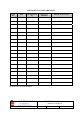


Table Of Contents
- AMENDMENT LIST RECORD SHEET
- INTRODUCTION
- 1.SAFETY CONSIDERATIONS
- 2.OVERVIEW/SYSTEM DESCRIPTION
- 3.SPECIFICATIONS
- 3.1Parts Lists
- 3.2Technical Specifications
- 3.2.1UHF ONE to Tunnels 1 & 2 Technical Specification
- 3.2.2UHF1A Technical Specification
- 3.2.3UHF ONE to Location TWO Technical Specification
- 3.2.4UHF TWO to Tunnels 1 & 2 Technical Specification
- 3.2.5UHF TWO to Location TWO Technical Specification
- 3.2.6800MHz Bi-directional Amplifier to Location TWO Technical Specification
- 3.3Mechanical Specification (UHF1/1A & UHF2 Wall Cases)
- 4.SYSTEM DRAWINGS
- 5.SUB-UNIT MODULES
- 5.1UHF 1 Air Interface (60-055901)
- 5.1.1Bandpass Duplexers (02-013401)
- 5.1.22 & 4 Way UHF Splitters (05-002603 & 05-003401)
- 5.1.3¼Watt 0- -30dB Switched Attenuator \(10-00
- 5.1.4Low Noise Amplifiers (11-006102, 11-007302 & 11-007402)
- 5.1.4.1General Description
- 5.1.4.2Technical Specification (11-006102)
- 5.1.4.3Drg. No. 11-006102, Low Noise Amplifier General Assembly
- 5.1.4.4Drg. No. 11-006170, LNA RF Circuit Diagram
- 5.1.4.5Drg. No. 11-006171, LNA DC Wiring Diagram
- 5.1.4.6Drg. No. 11-003971, LNA DC Schematic Diagram
- 5.1.4.7Technical Specification (11-007302)
- 5.1.4.8Drg. No. 11-007302, LNA Assembly With Alarm Relay
- 5.1.4.9Drg. No. 11-007370, LNA RF Circuit Diagram
- 5.1.4.10Drg. No. 11-007371, LNA DC Wiring Diagram
- 5.1.4.11Technical Specification (11-007402)
- 5.1.4.12Drg. No. 11-007402, LNA General Assembly
- 5.1.4.13Drg. No. 11-007470, LNA RF Circuit Diagram
- 5.1.4.14Drg. No. 11-007471 LNA DC Wiring Diagram
- 5.1.55Watt Power Amplifier (12-001801)
- 5.1.5.1Description
- 5.1.5.2Technical Specification
- 5.1.5.3Drg. No. 12-001801, 5Watt PA General Assembly Drawing
- 5.1.5.4Drg. No. 12-001870, 5Watt PA Circuit Diagram
- 5.1.5.5Drg. No. 12-001870C1, 5W PA Component List(1)
- 5.1.5.6Drg. No. 12-001870C2, 5W PA Component List(2)
- 5.1.5.7Drg. No. 80-008450, Power Amplifier/Alarm Board DC Wiring Details
- 5.1.63 Stage Amplifier Alarm Boards (12-002201)
- 5.1.7DC/DC Converter, 24V in, 12V 8A out (13-003011)
- 5.1.8Channel Selective & Channel Control Modules (17-003012 & 17-002101)
- 5.1.8.1Channel Selective Module Description
- 5.1.8.2Drg. No. 17-003080, Generic Channel Module Block Diagram
- 5.1.8.3Channel Selectivity Control Module Description
- 5.1.8.4Channel Controller DIP Switch Configuration Frequencies
- 5.1.8.5UHF1 Downlink Channel Module Configuration Table
- 5.1.8.6UHF1 Uplink Channel Module Configuration Table
- 5.1.8.7UHF1A Downlink Channel Module Configuration Table
- 5.1.8.8UHF1A Uplink Channel Module Configuration Table
- 5.1.8.9UHF2 Downlink Channel Module Configuration Table
- 5.1.8.10UHF2 Uplink Channel Module Configuration Table
- 5.1.9Single & Dual 24Volt Relay Boards (20-001602 & 80-008902)
- 5.1.10SMA coaxial termination (93-930003)
- 5.1.1124V 400W Flat-Pack Power Supply (96-300011)
- 5.2UHF 2 Air Interface (60-055902)
- 5.2.1Bandpass Filter (02-013401) See section 5.1.1
- 5.2.24 Port Tx Hybrid Combiner (05-003019)
- 5.2.3Four Way Low Power Splitter (05-003401) See section 5.1.2
- 5.2.4¼Watt 0- -30dB Switched Attenuator \(10-00
- 5.2.5Low Noise Amplifiers (11-007302 & 11-007402) See section 5.1.4
- 5.2.63 Stage Amplifier Alarm Boards (12-002201) See section 5.1.6
- 5.2.720Watt Power Amplifier (12-004201)
- 5.2.8DC/DC Converter, 24V in, 12V 8A out (13-003011) See section 5.1.7
- 5.2.9Chan. Selec. & Chan. Contr. Mdls (17-003012 & 17-002101) See section 5.1.8
- 5.2.1021MHz IF Filter Board (17-002502)
- 5.2.11Single & Dual 24Volt Relay Boards (20-001602 & 80-008902) See section 5.1.9
- 5.2.12SMA Coaxial Termination (93-930003) See section 5.1.10
- 5.2.1324V 400W Flat-Pack Power Supply (96-300011) See section 5.1.11
- 5.2.14JWS75-15/A PSU (96-300045)
- 5.2.15Single Mode Optical Coupler (98-100001)
- 5.2.16.Fibre Optic Receiver & Transmitter (98-200003 & 98-300003)
- 5.3UHF1A 60-055903 470MHz 3 Channel BDA
- 5.1UHF 1 Air Interface (60-055901)
- 6.INSTALLATION
- 7.MAINTENANCE
- APPENDIX AINITIAL EQUIPMENT SET-UP CALCULATIONS

PBL UHF1/1A 1 & 2 Air Interface
Maintenance Handbook
H/book Number:-60-055900HBKM
Issue No:-2
Date:-20/10/2003
Page:-
10 of 85
1.3 Chemical Hazard
Beryllium Oxide, also known as Beryllium Monoxide, or Thermalox™, is sometimes used
in devices within equipment produced by Aerial Facilities Ltd. Beryllium oxide dust can be
toxic if inhaled, leading to chronic respiratory problems. It is harmless if ingested or by
contact.
Products that contain beryllium are load terminations (dummy loads) and some power
amplifiers. These products can be identified by a yellow and black “skull and crossbones”
danger symbol (shown above). They are marked as hazardous in line with international
regulations, but pose no threat under normal circumstances. Only if a component containing
beryllium oxide has suffered catastrophic failure, or exploded, will there be any danger of the
formation of dust. Any dust that has been created will be contained within the equipment
module as long as the module remains sealed. For this reason, any module carrying the
yellow and black danger sign should not be opened. If the equipment is suspected of failure,
or is at the end of its life-cycle, it must be returned to Aerial Facilities Ltd for disposal.
To return such equipment, please contact the Quality Department, who will give you a
Returned Materials Authorisation (RMA) number. Please quote this number on the packing
documents, and on all correspondence relating to the shipment.
PolyTetraFluoroEthylene, (P.T.F.E.) and P.T.F.E. Composite Materials
Many modules/components in AFL equipment contain P.T.F.E. as part of the RF insulation
barrier.
This material should never be heated to the point where smoke or fumes are evolved. Any
person feeling drowsy after coming into contact with P.T.F.E. especially dust or fumes
should seek medical attention.