
User's Manual
12 Channel Channelised Cell Enhancer
User Handbook
Handbook N.-50-122501HBK Issue No:-A
Date:-16/03/05
Page:-
2 of 40
Table of Contents
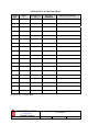
AMENDMENT LIST RECORD SHEET ...................................................................................................4
INTRODUCTION.........................................................................................................................................5
Scope ........................................................................................................................................................................... 5
Purpose ....................................................................................................................................................................... 5
Glossary of Terms...................................................................................................................................................... 6
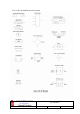
Key to AFL RF Module Drawing Symbols ............................................................................................................. 7
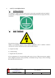
1. SAFETY CONSIDERATIONS.........................................................................................................8
1.1 Earthing of Equipment ................................................................................................................................ 8
1.2 Electric Shock Hazard.................................................................................................................................. 8
1.3 RF Radiation Hazard ................................................................................................................................... 9
1.4 Chemical Hazard ........................................................................................................................................ 10
1.5 Emergency Contact Numbers.................................................................................................................... 10
2. OVERVIEW/SYSTEM DESCRIPTION .......................................................................................11
3. SPECIFICATION ............................................................................................................................12
3.P Cell Enhancer Case Internal Photograph ................................................................................................ 12
3.1 Description .................................................................................................................................................. 13
3.2 Electrical Specification............................................................................................................................... 13
3.3 Mechanical Specification............................................................................................................................ 14
3.4 System Diagram, Drg. Nō. 50-122580 ....................................................................................................... 15
3.5 Generic System Case Outline Drawing..................................................................................................... 16
3.5 Parts List ..................................................................................................................................................... 17
4. SUB-UNIT MODULES....................................................................................................................18
4.1 3 Port Tx Hybrid Couplers (05-000103 & 05-000104) ............................................................................ 18
4.1.1 Description ............................................................................................................................................... 18
4.1.2 Technical Specification............................................................................................................................. 18
4.2 ¼Watt 0- -30dB Switched Attenuator (10-000703)..................................................................................19
4.2.1 General Application ................................................................................................................................. 19
4.2.2 Switched Attenuators ................................................................................................................................ 19
4.3 VHF/UHF Low Noise Amplifier (11-006002)........................................................................................... 20
4.3.1 Description ............................................................................................................................................... 20
4.3.2 Technical Specification............................................................................................................................. 20
4.3.3 LNA ‘D’ Connector Pin-out details.......................................................................................................... 20
4.4 10Watt Power Amplifier (12-002001) ....................................................................................................... 21
4.4.1 Description ............................................................................................................................................... 21
4.4.2 Technical Specification............................................................................................................................. 21
4.5 20Watt Power Amplifier (12-003601) ....................................................................................................... 22
4.5.1 Description ............................................................................................................................................... 22
4.5.2 Technical Specification............................................................................................................................. 22
4.6 DC/DC Converter, 24V in, 12V 8A out (13-003011) ............................................................................... 23
4.6.1 Description ............................................................................................................................................... 23
4.6.2 Technical Specification............................................................................................................................. 23
4.7 Channel Control Module (17-002101) ...................................................................................................... 24
4.7.1 Description ............................................................................................................................................... 24
4.7.2 Technical Specification............................................................................................................................. 24
4.7.3 VHF/ UHF Programming Procedure....................................................................................................... 25
4.7.4 VHF/ UHF Programming Example.......................................................................................................... 26
4.8 Channel Selective Module (17-009106)..................................................................................................... 27
4.8.1 Description ............................................................................................................................................... 27
4.8.2 Drg. Nō. 17-003080, Generic Channel Module Block Diagram.............................................................. 28
4.9 24V Relay Board (20-001602).................................................................................................................... 29
4.9.1 Description ............................................................................................................................................... 29