
User's Manual


12 Channel Channelised Cell Enhancer
User Handbook
Handbook N.-50-122501HBK Issue No:-A
Date:-16/03/05
Page:-
13 of 40
3.1 Description
The system consists of separate modules mounted within a lockable, environmentally
protected enclosure. It is designed to amplify twelve bi-directional channels (six uplink, six
downlink) of mobile signals operating in the VHF waveband. All twelve channel selective
modules are configurable for any frequency (within the channel modules’ designed range) set
by the DIP switches on the channel control modules – see section 4.8 for channel frequency
calculation examples. Alarms are provided for each amplifier and channel selective module
which are wired as a volt-free, relay isolated summary loop, terminating at pins 1 & 2 in the
external connector. The ‘normal’ condition is that each active device ‘holds’ a local relay
closed, (so if power fails, the alarms become active) making a fail-safe system.
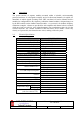
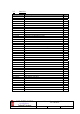
3.2 Electrical Specification
PARAMETER SPECIFICATION
Frequency range: 167.0-172MHz (Downlink)
162.0-165MHz (Uplink)
Channel module frequencies: Unspecified
Bandwidth: 3MHz uplink 5MHz downlink
Channel ripple: <±1.5dB
Gain: >95dB
Gain Adjustment: 0 - 30dB (in 2dB steps)
Spurious noise (in-band 30kHz): <-13dBm (U/L & D/L)
Uplink Power: >10.0Watts
Downlink Power: >40.0Watts
DownlinkO/P power/channel: +24dBm
UplinkO/P power/channel: +18dBm
Channel module gain: 30dB
-15.5dBm (downlink)
Channel module ALC:
-14dBm (uplink)
+44dBm (downlink)
PA 1 dB compression point:
+38dBm (uplink)
+56dBm (downlink)
PA IP3:
+50dBm (uplink)
Noise Figure: <6dB
VSWR: better than 1.5:1
RF Connectors: N type, female
Input supply power: 110 or 230V ac
operational:
-10°C to +60°C
Temperature range:
storage:
-40°C to +70°C
1 Amplifiers Alarms Fitted:
(volt-free contacts/TTL)
2 Channel modules