User Manual
Table Of Contents
- AMENDMENT LIST RECORD SHEET
- INTRODUCTION
- 1.SAFETY CONSIDERATIONS
- 2.OVERVIEW/SYSTEM DESCRIPTION
- 3.SPECIFICATION
- 4.SYSTEM DRAWINGS
- 5.SUB-UNIT MODULES
- 5.1Downlink Channelised Cell Enhancer 60-060602 (5U chassis)
- 5.1.1Bandpass Filters (02-010701)
- 5.1.2UHF 3dB Splitter (05-002603)
- 5.1.33dB UHF Splitter (05-002603)
- 5.1.4¼Watt 0- -30dB Switched Attenuator \(10-00
- 5.1.5Low Noise Amplifiers (11-007302 & 11-007402)
- 5.1.5.1Description
- 5.1.5.2Technical Specification, (11-007302)
- 5.1.5.3Technical Specification (11-007402)
- 5.1.5.3Drg. No. 11-007302, LNA Assembly With Alarm Relay
- 5.1.5.4Drg. No. 11-007370, LNA RF Circuit Diagram
- 5.1.5.5Drg. No. 11-007371, LNA DC Wiring Diagram
- 5.1.5.6Drg. No. 11-003971, LNA DC Circuit Diagram
- 5.1.610Watt Power Amplifier (12-001901)
- 5.1.73 Stage Amplifier Alarm Boards (12-002201)
- 5.1.8Dual DC/DC Converter (13-001803)
- 5.1.9Channel Selective Module (17-003012)
- 5.1.1024V Relay Board (20-001602)
- 5.2Uplink Channelised Cell Enhancer 50-060603 (5U chassis)
- 5.3Power Supply Shelf 50-060604 (4U chassis)
- 5.1Downlink Channelised Cell Enhancer 60-060602 (5U chassis)
- 6.INSTALLATION
- 7.MAINTENANCE
- APPENDIX AINITIAL EQUIPMENT SET-UP CALCULATIONS

5-Way Channelised UHF Cell Enhancer
Maintenance Handbook
H/book Number:-50-060601HBKM
Issue No:-
1
Date:-04/07/2003
Page:-
54 of 54
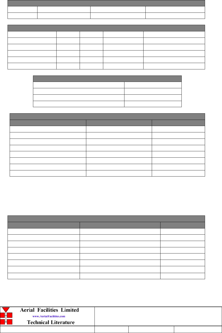
APPENDIX A INITIAL EQUIPMENT SET-UP CALCULATIONS
GENERAL INFORMATION
Site Name: Client Name:
Date: AFL Equip. Model N.
ANTENNA SYSTEMS
Model Gain Azimuth Comments
A - Service Antenna
B – Donor Antenna
Type Loss Length Comments
C – Service Feeder
D – Donor Feeder
INITIAL PARAMETERS
E – CE Output Power
dBm
F – Antenna Isolation
dB
G – Input signal level from donor BTS
dBm
Operating Voltage V
DOWNLINK CALCULATIONS
Parameter Comments Value
Input signal level (G)
dBm
CE max. o/p power (E)
dBm
Gain setting
E - G
dB
Isolation required (Gain + 10dB) dB
Service antenna gain (A)
dB
Service antenna feeder loss (C)
dB
Effective radiated power (ERP)
E+A-C
dBm
Attenuator setting CE gain-gain setting dB
If the input signal level in the uplink path is known and steady, use the following calculation
table to determine the gain setting. If the CE features Automatic Gain Control the attenuator
should be set to zero and if not, then the attenuation setting for both uplink and downlink
should be similar.
UPLINK CALCULATIONS
Parameter Comments Value
Input signal level dBm
CE max. o/p power (E)
dBm
Gain setting dB
Required isolation dB
Donor antenna gain (B)
dB
Donor antenna feeder loss (D)
dB
Effective radiated power (ERP)
E+B-D
dBm
Attenuator setting (CE gain-gain setting) dB


