Operating Manual (Rev. 1.3) Oxygen 5 Broadcast Console AXEL TECHNOLOGY S.R.L. Web site: www.axeltechnology.com E-mail: info@axeltechnology.
Oxygen 5 CONTENTS 1 INSTALLATION – MIXING CONSOLE OVERVIEW ......................................................................................4 1.1 2 STEREO MODULE .................................................................................................................................................5 2.1 2.2 2.3 2.4 2.5 2.6 2.7 2.8 2.9 2.10 2.11 2.12 2.13 3 INTRODUCTION ..........................................................................................................................
Oxygen 5 5.8 5.9 5.10 5.11 5.12 5.13 5.14 5.15 5.16 5.17 5.18 6 COMPRESSOR SECTION .................................................................................................................................27 SUB TO COMP SWITCH ....................................................................................................................................27 AUTO FADER SWITCH ............................................................................................................................
Oxygen 5 1 INSTALLATION – MIXING CONSOLE OVERVIEW • • • • • • • • Read carefully the present manual and conserve it Oxygen is conceived and built in conformity with the security laws in force. Please use high quality wires with good electric shield and balanced links wherever possible. The installation has to be carried on by skilled technicians. The images and the graphic layout showed on this manual could be slightly different from the ones printed on the modules. Axel Technology is at Yr.
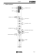
Oxygen 5 2 STEREO MODULE Input A REMOTE Interface Input B A-B Input Selector GAIN Control Equalization Section BALANCE Control MASTER and SUB switches PFL function START/STOP Button FADER Pag.
Oxygen 5 2.1 INTRODUCTION Stereo module is easily and readily configurable as line/line or line/phono depending on the user requirement. Input A is a line stereo input, while Input B (stereo) may be set through internal jumpers as line stereo or phono stereo (with built-in R.I.A.A. preamplifier). The module provides also a REMOTE interface to connect or control external equipment. Optoisolated connection pins assure the electrical immunity from external noises. 2.
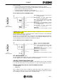
Oxygen 5 Please note that: § the max current value provided by the Start/Stop photo transistors is 20 mA. § Interface phototransistors are not able to directly drive any external relais. Please use them to drive an external power transistor . § Internal phototransistor impedance is about 150 Ω.
Oxygen 5 2.5 A-B INPUT SELECTOR It selects the input A (led switched off) without the pressed button; the input B (led switched on) with the pressed button. 2.6 GAIN CONTROL It sets the gain from -15dB to +15dB on the selected input (A or B). We suggest to set the gain so that the output audio signal is not distorted when the slider is on its upper point and so that the PFL level is 0 dB. 2.7 EQUALIZATION SECTION The equalisation section is based on three controls: LOW, MID ,HIGH operating from ± 15dB.
Oxygen 5 the Master module is pressed) the previous PFL is reset (i.e. it is not possible to listen to the sum of different PFLs). Press the PFL RESET key on the Master module to disable any PFL. PFL signal is available on the Master module, in the Control Room and Studio sections, where the PFL signal has priority on the other selections.
Oxygen 5 • Phono/line input B setting: see J1, J2, J3, J4, J5, J6 on figure • If J12, J13, J14 and J15 (placed at the bottom of the board) are in the Start/Stop configuration (INDIRECT mode), you can get the following functions: if J7 is present, the Start/Stop key starts up also the Timer 2 if J8 is present, the Start/Stop key starts up also the Relais 2 if J9 is present, the Start/Stop key starts up also the Relais 1 if J16 (Latch) is present, the interface features a permanent, optoisolated Start/Sto
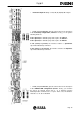
Oxygen 5 3 MONO MODULE Input A Input B Input A INSERT GAIN Input A Trimmer A-B Input Selector GAIN Control Equalisation Section PANORAMIC Control MASTER and SUB switches PFL button ON/OFF button FADER Pag.
Oxygen 5 3.1 INTRODUCTION The Mono module features two mono inputs (Input A and Input B). Input A is factory pre-set on microphone level but it can be also easily set on line level. Input B is set only on line level. 3.2 A INPUT Input A is electronically balanced on female XLR. Through jumper setting you can change the input A gain to fit the Micro level or the Line level; a fine gain adjustment only of the Micro level can be achieved through the trimmer ‘Gain input A’ (see GAIN INPUT A Trimmer).
Oxygen 5 3.6 GAIN INPUT A TRIMMER You can use the multi-turns trimmer to fit the Micro level to the input level of the preamplification circuit. It’s highly recommended if the Gain potentiometer doesn’t amplify or attenuate enough the Micro signal. Adjust the trimmer to reach the 0 dB PFL output level corresponding to the Gain control central position (read the level on the VU-Meter). Remember that through jumper setting you can change the input A gain to fit the Micro level or the Line level (see § 0).
Oxygen 5 3.11 MASTER AND SUB SWITCHES MASTER and SUB switches connect the module to the Master and/or Sub outputs. The leds inside the switches turn on according to the pressed buttons. By using the Master/Sub assignment, you could, f.i., record an interview to Yr guest in studio while another musical program is on air. To get this, please assign only to the Sub output the Mono channels involved in the recording session and to Master output the ones providing the on air program.
Oxygen 5 3.
Oxygen 5 3.16 MODULE CONFIGURATION On the MONO module board you find 10 Jumpers allowing different operation modes and functions.
Oxygen 5 If J1 is present, Phantom voltage is enabled on input A • If J2 is present, input A is set for MICRO level (otherwise is set on Line level) • If J3 is on ‘Fader Enable’ position, every time you open the slider (no matter of the On/Off key) the Studio monitor loudspeakers are cut off. • If J3 is on ‘On Enable’ position, when the module is in the ON state the Studio monitor loudspeakers are cut off. The On/Off switching mode is determined by the J8 position.
Oxygen 5 4 TELCO MODULE SEND Output REMOTE interface RECEIVE Input REC OUT Output SEND GAIN Control RECEIVE GAIN Control Equalisation Section PAN Control MASTER and SUB switches PRIVATE Button HOOK Button FADER Pag.
Oxygen 5 4.1 SEND OUTPUT The Send output allows to send to the telephone line - through an external phone hybrid (e.g. MACROTEL7 by AXEL Technology) - the signal composed by the sum of the output signals from every module except the Telco one. Send output (mono) is electronically balanced on female a Jack with 0 dB gain. The pin-out presents standard configuration: • Sleeve Ground • Tip Signal • Ring Return We suggest to use balanced links. See Appendix A for wire connection schemes. 4.
Oxygen 5 THE CONNECTOR SUPPLIES THE FOLLOWING VOLTAGES: • + 6 VDC (pin 6) • GND (pin 1) These voltages can be used to polarize external optoisolator devices. We suggest to use a 100 Ω (or more) resistor in series connection with the phototransistor emitter to prevent the risk of damages to the photocoupler, due to extra-high current. 4.
Oxygen 5 4.8 PANORAMIC CONTROL The PAN control allows sound balancing between Left and Right output channels. In the central position the gain is 0 dB for both channels. 4.9 MASTER AND SUB SWITCHES MASTER and SUB switches connect the module to the Master and/or Sub outputs. The led inside the switches turn on according to the pressed buttons. By using the Master/Sub assignment, you could, f.i., record a telephonic interview to Yr guest while another musical program is on air.
Oxygen 5 4.11 HOOK BUTTON If the telephone hybrid features the required functions (for this purpose, we suggest to use MACROTEL7 by AXEL Technology) and it’s correctly linked to the remote interface, you can: • receive the signalling of an incoming call (ring): the Hook led blinks. • ‘hook’ the telephone line by pressing the Hook button: the led lights firmly 4.12 FADER The slider is one of the most important device in the mixer.
Oxygen 5 J1 enables the recording of Send signal through the Rec Out socket. J2 enables the recording of Receive signal through the Rec Out socket. If J1,J2 are both present, Rec Out output provides the sum of Send/Receive signals. If J3 is on ‘Fader Enable’ position, whenever you open the slider the Studio monitor loudspeakers are cut off. If J3 is on ‘Hook Enable’ position, whenever you press the Hook button the Studio monitor loudspeakers are cut off. If J3 is not present, no function is featured.
Oxygen 5 5 SUB MODULE EXT IN Input INSERT REMOTE Interface SUB Output REC 1-2 Outputs EXTERNAL FADER switch EXT GAIN Control COMPRESSOR Section AUTO FADER switch SUB to COMP switch BALANCE Control EXT to MASTER switch SUB to MASTER switch PFL Button SLATE Button FADER Pag.
Oxygen 5 5.1 SUB OUTPUT The Sub output (mono) is electronically balanced on female Jack with 0 dB gain. This output provides the sum of the output signals from the modules (Mono, Telco, Stereo, Multi input) where the ‘SUB’ selection is active. The pin-out presents standard configuration: • Sleeve Ground • Tip Signal • Ring Return We suggest to use balanced links. See Appendix A for wire connection schemes 5.
Oxygen 5 Pin-out SUB D 9P female: Pin 1 GND Pin 2 Enables the Talk Back function if you supplies + 6 V Pin 3 DC DUCK: by feeding a 0 ÷ 6 V tension you can control the Sub VCA Pin 4 N.C. Pin 5 N.C.
Oxygen 5 • • The remote enabling of the Talk Back from Studio to Control Room. The level fading of the comprehensive output signal coming out from the Sub module (which can be assigned to the Master module by pressing the ‘Sub to Master’ button on the Sub module). In this way the speaker located in the Studio room can remotely control the enabling of his microphone and the Talk Back communications towards the Control Room.
Oxygen 5 5.10 AUTO FADER SWITCH AUTO FADER switch enables the automatic level adjustment of a signal (available on the input of the Sub module) depending on the level modulation of another signal (available on the input of the Master module). E.g.
Oxygen 5 5.15 SLATE BUTTON Through the SLATE button you can send to the Sub output the signal coming from the microphone built-in in the Master module or from one of the microphones linked to the Mono modules (if you set properly the Master e Mono modules). This function can be especially useful when you need to add ‘voice announcements’ at the beginning of the recorded programs (signal provided by the Sub output, eventually repeated by the two Rec Out sockets). 5.
Oxygen 5 5.18 MODULE CONFIGURATION If J5 is present, the PFL signal turns to an AFL (After Fader Listen) signal Pag.
Oxygen 5 6 MASTER MODULE TUNER Input MASTER Output STUDIO Output Power Supply Connector VU Meter Connector CONTROL ROOM Output STUDIO Section CONTROL ROOM Section PFL RST Button TALK BACK function Microphone STUDIO Headphone CTRL ROOM Headphone Pag.
Oxygen 5 6.1 MASTER OUTPUT The two output sockets are electronically balanced on female stereo Jack with 0 dB gain. The pin-out presents standard configuration: • Sleeve Ground • Tip Signal • Ring Return We suggest to use balanced links. 6.2 TUNER IN The TUNER IN input is set to Line level, electronically balanced on two female Jack. TUNER IN allow to connect to the mixer an external radio receiver to monitor the broadcast signal.
Oxygen 5 6.4 CONTROL ROOM SECTION The CTRL ROOM section allows the listening (on the studio loudspeakers and headphones) of the source selected by the four buttons TUNER, EXT, MASTER and PFL. If you press simultaneously two or more selections (e.g. Tuner and Master), you can listen to the sum of the selected sources. We remember that the EXT signal comes from the Sub module and that the Tuner level can be regulated through the related trimmer.
Oxygen 5 From Studio to CTRL Room: the related signal is available on the Ctrl Room loudspeakers and headphones. The Studio to Control Room communications are get through one or more microphones connected to the Mono modules (where the J9 jumper ‘T.B. to Ctrl Room’ is present). Note: if no PFL are called (but the PFL button on the Ctrl Room section is select), every time you press the Talk button the Master, Sub or Tuner selection are replaced by the Talk signal.
Oxygen 5 Please refer to the following figure and to the ‘Factory preset jumper configuration’ chapter at the end of this manual before altering jumper configurations. If J1 is present, the Master internal microphone is enabled for ‘Talk Back to Studio’ function Pag.
Oxygen 5 7 POWER SUPPLY FRONTAL VIEW REAR VIEW 7.1 AC VOLTAGE (110-220 VAC) Attention! Before starting the power supply, please check that the line supply voltage corresponds to that indicated in the rear of power supply. Power supply is ex-work set for 220 VAC (if not otherwise required).
Oxygen 5 7.2 CONNECTION BETWEEN CONSOLE AND POWER SUPPLY Attention! Before starting the power supply, please check that the line supply voltage corresponds to that indicated in the rear of power supply. The power cable features a SubD- 9 female connector (to link to the console) and a SubD15 male connector (to link to the power supply). The cable transfers also the signals related to the Relais 1 - 2 (included in the power supply box). 7.
Oxygen 5 8 VU METER 8.1 MIXER CONNECTION The MET connector placed on Master module transfers the supply voltages and the signals feeding the VU-METER and the (optional) TIMERs. The connector type is SubD- 9 female. Please make sure the Met connector is on site. 8.2 VU-METER OPERATION The two VU-Meter on the mixer cover show the Right and Left channel output level till a PFL is called by a module. In this case, the VU-Meter will show the PFL signal.
Oxygen 5 9 TIMER (optional) By request, up to two Timer modules are available to be installed on the mixer cover. The Timer feature the time count up showing minutes, seconds and tenth of seconds if time duration does not exceed 1 hour and hours, minutes and seconds if time duration exceeds 1 hour. In particular, you can associate the two timers to the opening of the slider on Mono modules and to the Start/Stop function of the Stereo modules.
Oxygen 5 11 FACTORY PRESET MODULE CONFIGURATIONS • The following images show the factory pre-set, standard jumper setting. Please refer to these images and to the relates chapters before altering jumper position. Please note: every intervention on the modules always requires the mixer switching off ! 11.
Oxygen 5 11.2 MONO MODULE – FACTORY PRESET JUMPER CONFIGURATION J1 not present J2 present (Micro input Level) _________________________________________ Module setting for STUDIO microphones. By default, every mono module (excluding the last one on the right) is factory preset for the Studio microphones (“Talk Back to Control Room” configuration) so we suggest to connect them to the microphones placed in the STUDIO.
Oxygen 5 11.3 TELCO MODULE – FACTORY PRESET JUMPER CONFIGURATION J1 is present J2 is present J8 is present Pag.
Oxygen 5 11.4 MASTER MODULE – FACTORY PRESET JUMPER CONFIGURATION J1 Not Present Pag.
Oxygen 5 11.5 SUB MODULE – FACTORY PRESET JUMPER CONFIGURATION Rec1 and Rec2 set as Master output Pag.
Oxygen 5 12 WARRANTY AXEL TECHNOLOGY S.R.L warrants products against defects in material and workmanship for a period of one year from the date of original purchase for use, and agrees to repair or, at our option, replace any defective item without charge for either parts or labour. This warranty is valid for the original purchaser only.
Oxygen 5 FIG. 3 Balanced microphone connection FIG. 4 Unbalanced connections for STUDIO / CTRL ROOM monitor loudspeakers FIG. 5 Unbalanced connection for STEREO module, EXT IN socket, TUNER IN socket Pag.