
User manual


Oxygen 4 Digital - from Axel Technology Phone +39 051736555, support@axeltechnology.com Page 21
9.1.2 LINE inputs
The Oxygen 4 Digital can connect 7 analog line inputs. The Input numbers 1-4 and 7 (front side) are stereo
inputs. Input 5 and 6 are MONO inputs, with on the same connector a cleanfeed output, so these inputs can
be used for a telephone-hybrid.
You can hook up a telephone-hybrid to both MONO inputs. When one of the MONO inputs is routed to a
module and the module is routed to the PROG, SUB or both, the cleanfeed function will be activated
automatically. When activated all of the signals on the PROG, SUB or both will be added to the cleanfeed 1
(mono input 5) or 2 (mono input 6) buss except for the input signal.
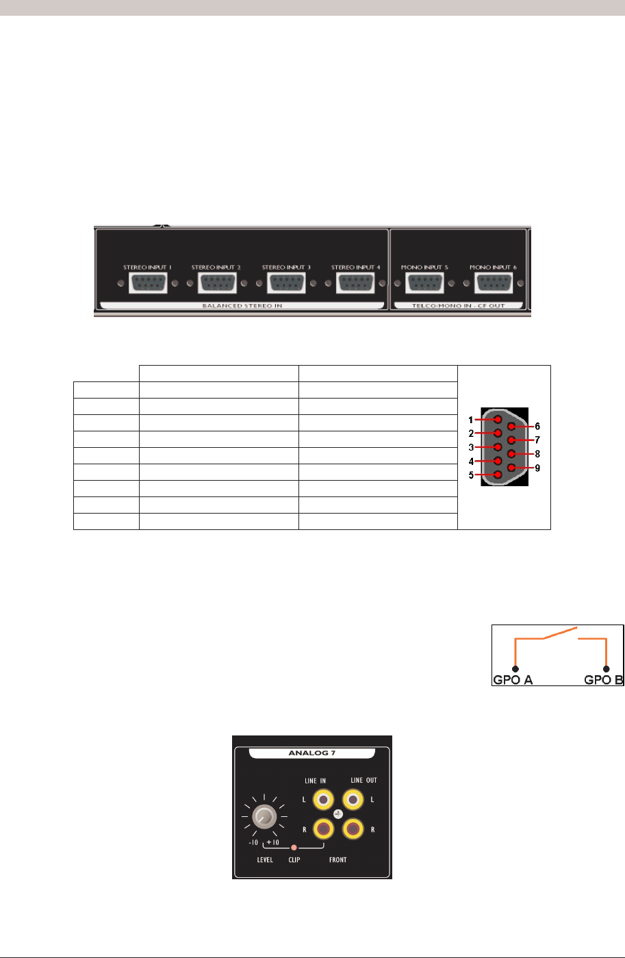
Below you see a picture of the rear view. Here you see all 9Pin SUBD connectors which you can use for
the analog inputs.
Figure 8: Analog Line Inputs at rear side
Stereo Input 1..4 Mono Input 5..6
Pin 1 Left + Mono IN +
Pin 6 Left - Mono IN -
Pin 2 GND GND
Pin 7 Right + Auto Cleanfeed OUT +
Pin 3 Right - Auto Cleanfeed OUT -
Pin 8 GND GND
Pin 4 GPO A GPO A
Pin 9 GPO B GPO B
Pin 5 Not Connected GPI
Table 4: Pinning for Stereo Input 1..4 and Mono Input 5..6
The GPI line on the MONO connectors can be used to connect the RING from your telephone-hybrid.
Usually the 'Ring' signal comes from a REMOTE on your Hybrid. Consult your telephone-hybrid manual for
information about how to connect the RING to the GPI of the MONO input.
GPO-A and GPO-B make connection if the GPO is activated!
Maximum current: 200 mA
Maximum resistance when connection made: 12 Ohm
Maximum Voltage: 24 V
At the front side of the 19” rack you can find one additional stereo analog input. Below you can see a picture
of this section. You have the ability to adjust the input level with the potentiometer located at the left side.
Figure 9: Analog Line Front Input