Oxygen 4 Digital Software version: Manual version: Oxy4DGT V1.0.0.5 - 18 Jun 2004 V1.
PRODUCT SAFETY PRODUCT SAFETY This product is manufactured with the highest standards and is double-checked in our quality control department for reliability in the "HIGH VOLTAGE" section. CAUTION Never remove any panels, or open this equipment. No user service-able parts inside. Equipment power supply must be grounded at all times. Only use this product as described, in user manual or brochure. Do not operate this equipment in high humidity or expose it to water or other liquids.
Replace fuses always with the same type and rating after the equipment has been turned off and unplugged. If the fuse blows again you have an equipment failure, do not use it again and return it to your dealer for repair. And last but not least be careful not to touch a person being shocked as you, yourself could also be shocked. Once removed from the shock, have someone send for medical help immediately Always keep the above-mentioned information in mind when using electrically powered equipment.
Dear Customer, Thank you for choosing the Oxygen 4 Digital Mixing console. The Oxygen 4 Digital is designed by specialists in the field of radio broadcast and designed to be used as a digital desktop mixer. The entire Axel Technology team is responsible for the design of the Oxygen 4 Digital. They always value suggestions from you once you have become familiar with your console.
1 INTRODUCTION ...................................................................................................................................7 2 CONTENTS OF THE PACKAGE..........................................................................................................8 3 START WORKING WITH THE OXYGEN 4 DIGITAL..........................................................................8 4 SYSTEM STRUCTURE.........................................................................................
10.4.5 CRM ...................................................................................................................................31 10.5 NETWORK SETTINGS THROUGH THE CONTROL SURFACE..............................................................32 10.5.1 Assigning an IP-address to the Oxygen 4 Digital ............................................................32 11 WEBPAGE ...........................................................................................................................
1 Introduction This manual will give you a detailed explanation of the functionality of the Oxygen 4 Digital and all its features. It is advised to read this manual once before touching any control, or even thinking about hooking up the system. We know that that is actually the firsts thing you want to do but please do NOT and discipline yourself to read the manual first.
2 Contents of the package The following parts should be inside the package. • • • • • • • 1x 19” Racks depending on the ordered configuration One or two 4-fader Control Surfaces or one 8-fader Control Surface depending on the ordered configuration 1 or 2 15Pins cable depending on the ordered configuration 1x Power cable 1x Crosslink network cable 1x CD-rom This manual 3 Start working with the Oxygen 4 Digital The internal power-supply is auto-sensing for the range of [85-264V/47-63Hz].
4 System structure The Oxygen 4 Digital system is a high-tech digital system, which is based on a 19” 2HE rack. In combination with the control surface(s) you will get a very easy to use console with many features that can work as a standalone unit and has a boot time of a couple of seconds (if network is disabled). The control surface(s) give you direct access to all the parameters you need to control in real time. Like the Fader level, routing and EQ/Dynamics.
5 Audio Signal Path Input Matrix Fader MIC 1..4 Module 1 EQ Dyn Module 8 EQ Dyn Sub CF2 CF1 Digital 1..7 Aux Pre CUE Mono Line 5,6 Aux Post Prog St Line1..4, 7 Cobra 1/2..31/32 Extern 1 Aux pre/post Dedicated Analog Outputs Extern 2 CRM CF1 CF2 Sub Prog Aux CUE Phones/Analog 7/Digital outputs 1-7 and Cobranet outputs 1/2-31/32 can select one of the (buss)outputs (or inputs = direct out) Figure 1: Audio Signal Flow 5.
5.3 Outputs For the Prog, Sub, Aux, Cleanfeed 1, Cleanfeed 2 and CRM busses, there are dedicated analog outputs. For all Digital outputs you have a separate router which makes it possible for you too choose which buss is connected to the digital output. Due to the advanced routing matrix you also have the option to route any input directly to an output. Oxygen 4 Digital - from Axel Technology Phone +39 051736555, support@axeltechnology.
6 Analog/Digital levels with the Oxygen 4 Digital Before you can start working with a (digital) console you need to understand all level standardization for the inputs and outputs. In the Analog domain it is sometimes confusing. But now we have to deal with even more formats. Often we use the following parameters: 0 dBu 0 dBFS Analog level of 0.775V at 600Ohm. FS= Full Scale (means maximum digital value, higher=clip).
To summarize things shortly: 0 dB on your meter is: • +6 dBu on the balanced input/outputs • 0 dBu on the unbalanced inputs/outputs • –20 dBFS fixed or -20 dBFS to 0 dBFS variable at the digital inputs/outputs. Oxygen 4 Digital - from Axel Technology Phone +39 051736555, support@axeltechnology.
7 Network Basics This chapter gives you a short overview on the network basics. This chapter is meant to give you some information about networking. When reading this chapter it's more easy to understand the technical backgrounds of the network possibilities. In general we can divide the network possibilities of the Oxygen 4 Digital in two types. WAN – Wide Area Network LAN – Local Area Network The first, WAN, is mostly based in TCP/IP (also known from the internet).
TCP/IP is a protocol that is well known in WAN structures. This means there are many Data Link & Physical Layers that can carry TCP/IP. In WAN structures the Cobranet protocol is not known, so that will only function on the Ethernet based networks. What happens if a destination of a TCP/IP envelope is outside the Ethernet network? The TCP/IP envelope will be redirected to the ‘gateway’.
7.3.2 Subnets and Subnet Masks A subnet is a part of a network that shares the same prefix. It enables a network administrator to further divide the host part of the address. Previously, another network number had to be requested from the Internet before a new network could be installed at a site. When a network is divided into subnets, a part of the host address is used to identify a particular subnet. Let’s look at an example: The network number is: 192.168.0 –or- 11000000.10101000.
7.3.5 DHCP DHCP stands for: “Dynamic Host Configuration Protocol”. DHCP is a TCP/IP service that you can use to set network clients' TCP/IP configurations automatically as they attach to the network. This configuration is done by providing the DHCP server with one or more scopes. A scope is nothing more than a range of IP addresses that may be assigned to clients on a temporary basis. The length of time that a client is allowed to use an IP address from a DHCP server is called the client's lease period.
8 Cobranet Basics This chapter gives you information for working with Cobranet. It's just a basic explanation of audio networking with Cobranet. For more information you can view the website http://www.peakaudio.com. 8.1 Cobranet Device A Cobranet Device has two RJ45 connectors which you can hook up to a switch or connect with a crosswire to another Cobranet Device. The reason for two RJ45 connectors is redundancy. It will function without problems if you connect just one RJ45 connector.
9 Hardware Connections This chapter will describe all connections to the 19” rack unit in detail. After this chapter you have all information to implement the system within your hardware. Some connections are software dependent and can be configured by software. Chapter 11 will explain everything on this settings. The Oxygen 4 Digital is equipped with Sub-D connectors. This way it is possible to have a lot of I/O in a small space.
Figure 7: Microphone inputs at rear side The MIC connections on the backside of the 19” rack are parallel with the XLR connections at the front side of the 19” rack. Warning: Phantom power is also applied to these connectors. (Don't short pins while phantom power is on.) At the back side you can find the four microphone inserts on a jack type connector.
9.1.2 LINE inputs The Oxygen 4 Digital can connect 7 analog line inputs. The Input numbers 1-4 and 7 (front side) are stereo inputs. Input 5 and 6 are MONO inputs, with on the same connector a cleanfeed output, so these inputs can be used for a telephone-hybrid. You can hook up a telephone-hybrid to both MONO inputs. When one of the MONO inputs is routed to a module and the module is routed to the PROG, SUB or both, the cleanfeed function will be activated automatically.
9.1.3 External inputs The Oxygen 4 Digital can sum two external inputs to the CRM buss. The sources for the external busses can be selected by using the web server. 9.1.4 Program/Sub/Aux/CRM outputs The Oxygen 4 Digital is a very intuitive mixer which is very similar to analog mixing consoles. Therefore you also have all common outputs in the analog domain. That means you can directly hook up your equipment. Below you see a picture of the connections available.
Figure 11: Phones output at 19" rack 9.2 Digital Inputs/Outputs The Oxygen 4 Digital holds 7 digital inputs and outputs. At the rear side of the 19” rack you will find digital I/O 1-6 and at the front side is Digital I/O 7 located. The digital inputs at the rear side can receive either Coax (SPDIF) or XLR (AES3) digital audio.
9.3 Global Inputs/Outputs 9.3.1 GPIOs The in-/outputs can be used for global functionality for example synchronization, remote function, relay logic etc… Each Sub-D connector represents 2 GPIO's.
9.3.3 On-Air Output The GPO on the CRM connector responds only to the Redlight1 buss. See ‘Table 5: Pinning for PROGRAM, SUB, AUX and CRM’ for the pinning of the connector. Figure 16: Redlight GPO 9.3.4 RS232 The RS232 port located on the backside of the Oxygen 4 Digital is for future use. Figure 17: RS232 at rear side 9.3.5 Ethernet The Ethernet connection of the Oxygen 4 Digital enables you to connect the device to your local network or directly to your PC.
9.3.6 Connection to Control Surfaces The control-unit(s) can be connected to the control-unit 1 and 2 connector. The surface connected to connector ‘TO CNTRL UNIT 1’ will always contain module 1-4 and the surface connected to connector ‘TO CNTRL UNIT 2’ will always control module 5-8.
9.3.7 Cobranet (optional) CobraNet operates on a switched Ethernet network or on a dedicated Ethernet repeater network (the last is not recommended). CobraNet provides the possibility to send and receive real-time digital audio data over an Ethernet network. The CobraNet interface has provisions for carrying and utilizing control and monitoring data such as Simple Network Management Protocol (SNMP) through the same network connection as the audio.
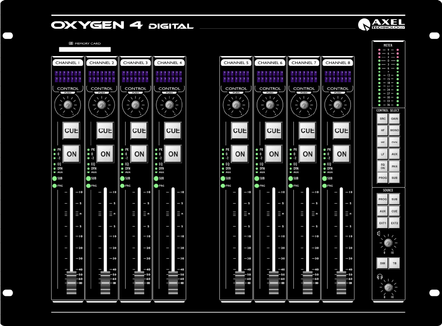
10 Using the Control Surface Figure 21: The 4-fader Control Surface of the Oxygen 4 Digital It is possible to process 8 stereo channels in parallel. Every processing channel handles source selection, mono, EQ, dynamics, level and routing selection. Now we shall give you a global overview of the Oxygen 4 Digital. All hands on features described here can be found on the control surface of the system. Next to the 4-fader version of the Control Surface there is also an 8-fader version available.
Figure 22: The 8-fader Control Surface of the Oxygen 4 Digital Oxygen 4 Digital - from Axel Technology Phone +39 051736555, support@axeltechnology.
10.1 Input routing The input signal can be processed as soon as it is converted into the digital domain by specifying an input source for the module. Selecting the source button on the control surface can do this. Now you can use the encoders to select/scroll through the inputs for a module. After pressing the gain button you can use the encoders to adjust the input level from -20dB to +20dB. The MIC inputs have a gain range of 0dB to +60dB.
10.4 Buss Routing When the signal has been processed in EQ, dynamics range and level, it can be routed to one or more busses such as the Aux. buss, Program buss, Sub buss and the stereo CUE buss. A description of the individual busses is written below. 10.4.1 Program/Sub buss The Oxygen 4 Digital has a stereo Program and Sub buss implemented. To route a channel to the Prog or Sub buss, you can select the Prog or the Sub button and push the encoder on a module.
10.5 Network settings through the Control Surface The Oxygen 4 Digital is a stand-alone mixer. That means that there is no need for a PC during operation. But before you start using the Oxygen 4 Digital you may want to make some settings regarding output routing or GPIO usage. You can connect your Oxygen 4 Digital directly to your PC by a cross-link cable or connect your Oxygen 4 Digital to your local network (Straight CAT5 UTP cable) and use a PC on the network to connect to the Oxygen 4 Digital. 10.5.
11 Webpage The control surface of the Oxygen 4 Digital covers all the basic routing and signal processing per channel. To control all the features of the Oxygen 4 Digital we need software tools. The software part of the Oxygen 4 Digital is a dynamic webpage that is inside the 'brain' of the console. By using it inside a network or on a stand-alone PC you can make all kinds of advanced settings to control and setup the Oxygen 4 Digital.
11.2 System information The System information screen displays the general status of the Oxygen 4 Digital. Figure 24.02: System Information Name/Description Location Contact Displays the networking name for the Oxygen 4 Digital. Displays the name of the location where the Oxygen 4 Digital is active. Displays the name of the person here who has administrator privileges on the Oxygen 4 Digital.
11.3 Network Settings The Network Settings screen of the Oxygen 4 Digital displays the settings that can be made regarding network usage. Figure 25.03: Network Settings Name/Description Location Max 64 Contact You can enter a networking name for the Oxygen 4 Digital. Max 64 characters. You can enter the name of the location where the Oxygen 4 Digital is active. characters. You can enter the name of the person here who has administrator privileges on the Oxygen 4 Digital. Max 64 characters.
Gateway Lets you change the gateway address. This address can only be changed if the DHCP option is disabled. Local Date - Time Displays the time retrieved from a NTP timeserver. NTP means Network Time Protocol. This is a standard protocol which is used to transmit UTC-time to clients. For more information you can visit http://www.ntp-time-server.com/. For the correct time to display you need to set the corresponding time zone.
11.4 Cobranet Settings The Cobranet settings page displays the global settings for the Cobranet module. Figure 26.04: Cobranet Settings Firmware version Displays the current firmware version inside the Cobranet module. MAC Current IP Static IP to use Displays the MAC address of the Cobranet module. Displays the current IP address in use by the Cobranet Module. Lets you adjust the current IP address of the Cobranet module. You must reset the console for changes to take effect.
Read/Write Community The read/write community is a password protection against read or writes requests through the SNMP protocol. The table displays the status and settings for the CobraNet module. There are 4 transmitting channels (TX) and 4 receiving channels (RX). Each channel consists of 8 sub-channels. Inside each sub-channel we can store 1 mono audio-source at 48kHz. The bundle-number represents an addressing-number. This number can vary between 256 and 65535 (unicast bundles).
11.5 Global Settings In the global setting screen you can make all kinds of basic settings. Figure 27.05: Global Settings Clock Source Clock source lets you choose the clock to which you want to synchronize the Oxygen 4 Digital. You can choose the following sources. 32 kHz internal 44.1 kHz internal 48 kHz internal Extern 48 kHz Cobranet The clock frequency chosen is also the clock which is on the Word-clock OUT. Note: If you are using Cobranet you have to select 48 kHz Cobranet clock.
CRM interlock CRM Dim CUE to CRM Dim EQ Range Aux Pre Extern1/2 Talkback MIC If this option is enabled you can only route one buss at a time to the CRM buss. You can set the amount of dimming you want on the CRM buss when pressing the DIM button one the Control-surface. (0 to -144dB) When activating a CUE when CUE to CRM is active, the signal level on the CRM buss will be dimmed by the specified value (0 to -144dB). The EQ range indicates the range that the three EQ levels can be adjusted.
11.5.2 GPO 1 to 6 The GPO sends trigger-signals to other devices. Figure 29.07: General Purpose Output (GPO) Continuous On Pulse Off Pulse Type GPO is the action state. (If action redlight is active, GPO is active) GPO pulses when action becomes active GPO pulses when action becomes inactive MIC1..4 Redlight1..2 RemoteBuss 1..4 Action The activation of MIC1..4 triggers the GPO The activation of Redlight1..2 triggers the GPO The activation of Remote Buss 1..
11.6 Input Settings The input settings menu is displayed in the next figure: Figure 30.08: Input Settings In this menu you can see all the inputs of the Oxygen 4 Digital. You can adjust the corresponding label per input. Each of the inputs has its advanced settings. If Cobranet is not installed the “Cobranet input settings” menu is not available. Oxygen 4 Digital - from Axel Technology Phone +39 051736555, support@axeltechnology.
11.6.1 Advanced input settings Figure 31.09: Advanced input settings The 'Advanced Input Setting' screens for the analog inputs, the digital inputs and the Cobranet inputs are the same except for a few option, which are grayed out if the function is not present. The settings for the MIC inputs are also the same except for one section. Phase Swap L/R L to LR R to LR Input Correction Inverts the phase of the signal. Exchanges the left and the right audio channel.
Local Function Audio On/Off enables you to disable the audio function of the On switch. This way you can use the On switch only to trigger the remote. Trigger On Remote causes a trigger when the channel is enabled by On switch. Trigger Off remote causes a trigger when the channel is disabled by the On switch. Note: When the audio function is disabled you will get a retrigger signal when pressing the ON switch regardless the settings for trigger On/Off remote.
11.7 Cobranet input Settings If Cobranet is not installed the “Cobranet input settings” menu is not visible. Figure 32.10: Cobranet Input Settings The idea behind the Cobranet Input Settings is basically the same as the normal Input Settings. Each bundle pair represents one 48kHz stereo channel. You can rename each label for your own purposes. Oxygen 4 Digital - from Axel Technology Phone +39 051736555, support@axeltechnology.
11.8 Output Settings Figure 33.11: Output Settings The Output Settings enables you to route inputs or busses to the outputs. The labels of the outputs can be renamed for specific purposes. If Cobranet is not installed “Cobranet output settings” menu is not visible. Each output has three settings. Conference Talkback Studio Mute CRM Mute The “Talkback MIC” selected in the Global Settings menu will be put through directly to the output with the [Conf. TB] setting activated.
11.8.1 Advanced Output Settings Figure 34.12: Output Settings The setting for the analog and digital outputs are nearly identical. The only difference can be found in the bit settings of the digital outputs and the Cobranet outputs. Source Selection You can select what kind of routing you want to the output. You can select any of the inputs to be directly routed to an output. You can also select a buss to be routed to an output. You can select PROG,SUB, AUX, CUE and CRM at -20dBFS.
11.9 Cobranet Output Settings If Cobranet is not installed “Cobranet output settings” menu is not visible. Figure 35.13: Cobranet Output Settings Each bundle pair represents a stereo audio-signal and can be renamed for specific purposes. Just like the normal Output Settings there are also three options per bundle pair available. Conference Talkback, Studio Mute and CRM Mute. These three options are already discussed in chapter 11.8. The Advanced Cobranet Settings menu is already discussed in chapter 11.8.
11.10 Security Settings The security setting of the Oxygen 4 Digital gives users the option to secure the Oxygen 4 Digital against misuse of any kind. It's possible to create a database of multiple users who have all kind of different accesslevels to the Oxygen 4 Digital. Users names can be stored on personal chip-cards. The chip-cards can be used to allow access to the control-surfaces. The chip-cards are fully compatible with the other AXEL TECHNOLOGY products like the Sirius and the Scorpius.
11.10.1 Users and Levels Figure 37.15: User and Level Settings The User and Level menu gives the user the option create or alter user accounts for the Oxygen 4 Digital. In the 'change settings' menu you can adjust the name and the security level of the user. You can also assign a password to the user. Note: The password is case sensitive. Each user has the ability to store his personal settings made on the control-surface and in the Global Settings menu.
Global Settings - EQ Range Aux PRE/POST Extern 1/2 Figure 38.16: User Settings To delete a user simply empty the username and the password field and change the level back to operator. There are 6 different user-levels in the Oxygen 4 Digital. System Administrator Supervisor Operator 1 Operator 2 Unknown Idle This level is the absolute highest you can assign to a user. This level has fixed privileges and can't be limited. This is a user definable level. This is a user definable level.
11.11 Chipcard Settings Figure 39.17: Chipcard Settings You can use this menu to program or reprogram chip-cards. When creating a user on the chip-card you must make sure that the user is also in the database. If not the user will be identified as 'Unknown'. In this case you will have no privileges on the control-surface. If you have a second control surface you can choose which modules chip card overrules the other.
11.12 Control Surface Levels Figure 40.18: Control Surface Levels The control-surface settings enable you to assign privileges to 5 different user-levels. You can set the following functions for each user-level. Control Surface 1 Control Surface 2 Encoder Function Network Setup Input Routing Gain Mono EQ Dynamics Aux Pan Buss Routing With this option you can enable/disable users to access the control surface 1. With this option you can enable/disable users to access the control surface 2.
11.13 Input Pool Levels Figure 41.19: Input Pool Levels The Input Pool Level Setting menu enables you to prevent users will access the inputs from the controlsurface. This option is also available for the Cobranet input channels if Cobranet is available in your Oxygen 4 Digital. Oxygen 4 Digital - from Axel Technology Phone +39 051736555, support@axeltechnology.
11.14 Network Levels With the network levels setup you can deny users certain menus and options on the webpage. You can also deny specific privileges on the FTP server and refuse connection to the ActiveX application. Figure 42.20: Network Levels System Information Network Settings Cobranet Settings Global Settings Input Settings Output Settings Security Settings HTTP Grants user-level permissions to access the System Information menu. Grants user-level permissions to access the Network Settings menu.
12 FTP The Oxygen 4 Digital also contains a FTP server (File Transfer Protocol) which may be used to transfer files from and to your PC. The information you can exchange is stored in three directories: Presets, Security, Flash. Depending on your rights given in the security section of the web-pages, you are able to browse and download/upload files.
13 Oxygen 4 Digital EQ Tool The Oxygen 4 Digital has a 3 band fully parametric equalizer. The gain can be adjusted on the controlsurface. The gain for each band can be set independently on each channel. The other two parameters, Frequency and Bandwidth, are adjustable but are the same for all the channels. To adjust the frequency and bandwidth parameters you can use the Oxygen 4 Digital EQ Tool located on the CDROM.
14 ActiveX Application The ActiveX application is a utility which allows you to control the Oxygen 4 Digital from a remote area. The application is a graphical user interface which displays a combination of the 2 control-surfaces. You have exactly the same options as 2 control surfaces together. Figure 44:The ActiveX application In the picture above you can see an overview of all the module-settings from both of the controlsurfaces together. The application works parallel with the control-surfaces.
15 Specifications 15.1 General system parameters Level specs in dB Full Scale for digital and dBu for analog data. 0dBu=0.775Vrms Sampling rate: 32kHz, 44.1kHz, 48kHz, 50ppm (when internally synchronized). Headroom: 20 dB 15.2 A/D and D/A Converters A/D Burr Brown/Texas Instruments 24 bit Delta Sigma Dynamic range: typically 112 dB THD+Noise: <-102 dB D/A Burr Brown/Texas Instruments 24 bit Advanced Segment Dynamic range: typically 113 dB THD+Noise: <-100 dB (0.001%) 15.3 Microphone Inputs Mic INP. Bal.
15.7 Digital Outputs AES/EBU/AES3, S/P-DIF, Optical (Toslink) active at the same time. 16/20/24 bit, 32kHz to 48kHz (System clock). Output level: 2 to 5 volts Output impedance: 110 Ohm Clock output: 75 Ohm TTL. 15.8 System Clock System clock internally 32kHz, 44.1kHz, 48kHz, 50ppm. Frame clock out: BNC 75 Ohm TTL Frame clock in: BNC 75 Ohm terminator switch, TTL 32kHz to 48kHz 15.9 Remotes All channel remotes are isolated on relays and interfaced on 9 pin Sub-D connectors.
DECLARATION OF CONFORMITY Manufacturers Name: Axel Technology Manufacturers Address: Axel Technology srl Via Caduti di Sabiuno 6/F 40011 Anzola Dell’Emilia ITALY Declares that the product Oxygen 4 Digital conforms to the following product specifications: EMC: NEN-EN 55103-1 NEN-EN 55103-2 NEN-EN 55013-1 1995 1995 1994 Supplementary Information: The products herewith complies with the requirements of the EMC Directive 89/336/EEC (1989) as amended by the CE Marking Directive 93/68/EEC (1993).
Dear Oxygen 4 Digital owner, In this manual we have tried to give you an overview of all that the Oxygen 4 Digital has to offer. As it is our policy to continuously improve on our products, this manual will be updated regularly. Please visit our web site http://www.axeltechnology.it/ to download the latest version of this manual. If you have any questions, do not hesitate to contact us. We wish you many years of enjoyable mixing. Best regards, Giuseppe Vaccari, President.
16 List of Figures Figure 1: Audio Signal Flow..........................................................................................................................10 Figure 2: OSI Model ......................................................................................................................................14 Figure 3: Network Implementation ...............................................................................................................14 Figure 4: Star Network...............
17 List of Tables Table 1: Level Definitions .............................................................................................................................12 Table 2: Pinning MIC Input 4-3 and MIC Input 2-1 ......................................................................................20 Table 3: Pinning Inserts ................................................................................................................................20 Table 4: Pinning for Stereo Input 1..
18 Glossary dBFS.................................................................13 dBu ...................................................................13 DHCP ...............................................................18 hybrid ................................................................22 IP.................................................................10; 16 IP Address ........................................................16 levels...........................................................
19 Appendix 19.1 Appendix A: Blockdiagram of the Oxygen 4 Digital The picture below represents the Oxygen 4 Digital. Basically there are two main blocks. The Mixing Console and the I/O Matrix. The Mixing console is the section where all the audio-processing takes place. The I/O Matrix is a very advanced matrix which gives you not only the possibility to route the busses to the outputs, but also the possibility to route any input directly to an output without interference from the Mixing Console.
19.2 Appendix B: Oxygen 4 Digital ActiveX Scripts Properties: Unsigned char *IP //eg. Format: “XXX.XXX.XXX.XXX” Bool Visible //Makes the object 1=Visible/0=Invisible Bool Active //Specifies whether the object is active and has focus Bool Enabled //Controls whether the object responds to mouse events. Int Left //Specifies the horizontal coordinate of the left edge of a component //relative to its parent.
//1 = Unknown user //2 = Operator 1 //3 = Operator 2 //4 = Supervisor //5 = System Administrator OnRemoteBuss1(long State) //If the Remote Buss 1 changes, its gives the new state with this event OnRemoteBuss2(long State) //If the Remote Buss 2 changes, its gives the new state with this event OnRemoteBuss3(long State) //If the Remote Buss 3 changes, its gives the new state with this event OnRemoteBuss4(long State) //If the Remote Buss 4 changes, its gives the new state with this event OnRedlight1(long State)
Void SetGain(long ModuleNr, long Value) //Set Gain at ModuleNr, Value may be -20 dB till 20 dB //For Source 0-3 = MIC1-MIC4: Value may be 0 dB till 60 dB Void SetEQHigh(long ModuleNr, long Value) //Set EQ High at ModuleNr, Value may be -18 dB till 18 dB Void SetEQMid(long ModuleNr, long Value) //Set EQ Mid at ModuleNr, Value may be -18 dB till 18 dB Void SetEQLow(long ModuleNr, long Value) //Set EQ Low at ModuleNr, Value may be -18 dB till 18 dB Void SetDynamics(long ModuleNr, long Value) //Set Dyn at Modul
//Set Remote buss on or off // RemoteBussNr = 0 -> buss 1 //... // RemoteBussNr = 3 -> buss 4 Long GetSource(long ModuleNr) //Get ModuleNr Source, Source may be 0 till 34 //0 = N.C.
//returns –140dB till 10dB Long GetCRMLevel() //returns –140dB till 10dB Long GetProgToCRM() //returns 1=ON/0=OFF Long GetSubToCRM() //returns 1=ON/0=OFF Long GetAuxToCRM() //returns 1=ON/0=OFF Long GetCUEToCRM() //returns 1=ON/0=OFF Long GetExt1ToCRM() //returns 1=ON/0=OFF Long GetExt2ToCRM() //returns 1=ON/0=OFF Long GetCRMDim() //returns 1=ON/0=OFF Long GetTB() //returns 1=ON/0=OFF Oxygen 4 Digital - from Axel Technology Phone +39 051736555, support@axeltechnology.
20 Disclaimer Due to a policy of continuous product improvement, AXEL TECHNOLOGY, reserves the right to change specifications, appearance and performance without prior notice. Since the use of this information, and the conditions by which the products are used are beyond the control of AXEL TECHNOLOGY, it is the obligation of the owner and/or the equipment operator to determine the correct and safe selection, settings and conditions of use of the equipment and products.