Oxygen 3 / 3ST Broadcast Mixing Console Operating manual (Rel. 1.2) Via Caduti Di Sabbiuno 6/F - 40011 Anzola Emilia - Bologna - Italy Tel. +39 051 736555 - Fax. +39 051 736170 e-mail: info@axeltechnology.com - web site: www.axeltechnology.
CONTENTS ENG 1 CONTENTS 2 SAFETY INSTRUCTIONS..................................................................................................................... 4 3 OXYGEN 3 SERIES - OVERVIEW........................................................................................................ 5 4 OXYGEN 3 – AUDIO INPUT CONNECTIONS ...................................................................................... 6 4.1 CH 1 to 3.................................................................
SAFETY INSTRUCTIONS ENG 2 SAFETY INSTRUCTIONS Read instructions: Retain these safety and operating instructions for future reference. Adhere to all warnings printed here and on the console power unit. Follow the operating instructions printed in this operating manual. Do not remove covers: Operate the power unit with its covers correctly fitted. Refer any service work to competent technical personnel only.
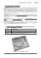
OXYGEN 3 SERIES - OVERVIEW ENG 3 OXYGEN 3 SERIES - OVERVIEW Oxygen 3 quality. The Oxygen 3 and 3 ST are specially designed On-Air broadcast consoles. Although the design has been carefully budgeted, no compromises has been made in either quality or features. Electronic components have been selected from the best on the market. Faders, potentiometers and switches are by ALPS.
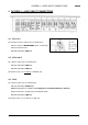
OXYGEN 3 – AUDIO INPUT CONNECTIONS ENG 4 OXYGEN 3 – AUDIO INPUT CONNECTIONS 4.1 CH 1 to 3 The first three channels feature two selectable inputs: - INPUT A: input for MICROPHONE signal, electronically balanced on XLR female - INPUT B (PIN RCA): LINE input. 4.2 CH 4 and 5 The channels feature two selectable inputs: - INPUT A (PIN RCA): LINE input. - INPUT B (PIN RCA): LINE input (the A input can be set, if required, as PHONO, too). 4.
OXYGEN 3 ST – AUDIO INPUT CONNECTIONS ENG 5 OXYGEN 3 ST – AUDIO INPUT CONNECTIONS 5.1 CH 1, 2 and 3 The first three channels feature two selectable inputs: - INPUT A: stereo LINE input electronically balanced on Jack 1/4” female. - INPUT B: mono input for MICROPHONE signal, electronically balanced on XLR female 5.
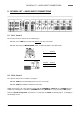
TELEPHONE CONNECTIONS (OXYGEN 3 and 3 ST) ENG Jumper setting LINE / PHONO on the INPUT B / Channel 4,5 & 6 Stereo input board (Oxygen 3 ST) 6 TELEPHONE CONNECTIONS (OXYGEN 3 and 3 ST) The Telephone module features a built-in telephone hybrid. The audio sent to the telephone caller is a mix-minus (N-1). The mix minus signal is the programme output signal with the phone signal (caller’s voice) removed.
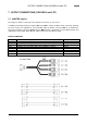
OUTPUT CONNECTIONS (OXYGEN 3 and 3 ST) ENG 7 OUTPUT CONNECTIONS (OXYGEN 3 and 3 ST) 7.1 MASTER outputs The Oxygen 3’s Master section gives the operator an extensive set of resources.
OUTPUT CONNECTIONS (OXYGEN 3 and 3 ST) 7.2 ENG MONITOR OUT and EXT-IN connections (OXYGEN 3 and 3 ST) The Oxygen 3’s Monitor section gives the operator an extensive set of resources. In addition to monitoring the Master and PFL audio buses, provision has been made for monitoring an external audio source. This stereo input (Ext-In) is intended to be connected to microwave, FM or satellite receivers or another studio.
OXYGEN 3 – INPUT MODULE DESCRIPTION ENG 8 OXYGEN 3 – INPUT MODULE DESCRIPTION 8.1 CHANNELS 1 to 6 A/B SWITCH: The B SEL switch selects the INPUT B socket when depressed and the INPUT A when released. A LED glows green when the INPUT B is selected. Input A is set for Micro level on Channels 1 to 3, for Line level on the Channels 4 and 5 and for Phono level on the Channel 6 if not otherwise indicated.
OXYGEN 3 ST – INPUT MODULE DESCRIPTION ENG 9 OXYGEN 3 ST – INPUT MODULE DESCRIPTION 9.1 CHANNELS 1 to 6 A/B SWITCH: The B SEL switch selects the INPUT B socket when depressed and the INPUT A when released. A LED glows green when the INPUT B is selected. Input B is set for Micro level on Channels 1 to 3, for Line level on the Channels 4 and 5 and for Phono level on the Channel 6 if not otherwise indicated.
TELEPHONE CHANNELS (OXYGEN 3 and 3 ST) ENG 10 TELEPHONE CHANNELS (OXYGEN 3 and 3 ST) The Telephone module features a built-in telephone hybrid. The module features two gain controls, PFL, Master output, hybrid Hook / Ring controls. It features connections to a regular telephone line (POTS) and to an external standard telephone set (f.i. for dialling). Automatic line compensation is also featured. The audio sent to the telephone caller is a mix-minus (N-1).
TELEPHONE CHANNELS (OXYGEN 3 and 3 ST) ENG The scale shows the attenuation. Normal operating position is at the top ‘0’ mark, providing overall 0 dB of gain. On request, to notify at order, ALPS K series sliders can be also fitted. The benefit is longer fader life and more reliable operation. 10.1 ALIGNEMENT OF INPUTS When plugging in a new source start with the fader turned down and the PFL activated.
OUTPUT MODULES DESCRIPTION (OXYGEN 3 and 3 ST) ENG 11 OUTPUT MODULES DESCRIPTION (OXYGEN 3 and 3 ST) 11.1 MASTER section OUTPUT 1: it controls the signal level on the output labelled OUTPUT 1 (balanced). OUTPUT 2: it controls the signal level on the output labelled OUTPUT 2 (balanced). BALANCE: it controls the signal balance on the outputs labelled OUTPUT 1-2-3 and FIXED. OUTPUT 3: it controls the signal level on the output output labelled OUTPUT 3 (unbalanced). 11.
OUTPUT MODULES DESCRIPTION (OXYGEN 3 and 3 ST) ENG Monitor Speaker Mute The Mute function (Monitor speaker cut off) always operates whenever Channel 1 (MicDJ / Line) is used (i.e. the fader is opened). This is to prevent acoustic feed-back (e.g. using a Studio microphone). MUTE function never affects headphone monitoring section. SOURCE SELECTION BUTTONS The core of the monitor section are the two monitor source buttons.
BLOCK DIAGRAM (OXYGEN 3) ENG 11.4 LED-METERS The Oxygen 3 and Oxygen 3 ST mixers are fitted with VU / PEAK LED meters. VU meters respond to an average signal level, whereas PEAK LED glows when the 0dB threshold is overpassed (it remains ‘on’ long enough to provide easy recognition). The VU meters are factory-calibrated and no further user adjustement is allowed. A short cable with a 9 pins subD plug on each end (male and female) comes with the console. It is used to connect the meterbridge to the mixer.
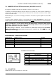
TECHNICAL SPECIFICATIONS ENG 13 TECHNICAL SPECIFICATIONS 13.1 OXYGEN 3 LINE-LINE & LINE – PHONO STEREO MODULE INPUT A Stereo INPUT A levels 0 dBm (LINE – Channels 4 - 5) Phono (RIAA – Channel 6) INPUT A impedance (line) 10 kOhm PinRCA Unbal Unbal -12 to +12 dB gain control -12 to +12 dB gain control INPUT B INPUT B nominal level INPUT B impedance Stereo 0 dBm (LINE) 10 kOhm Unbal PinRCA MONO/STEREO MODULE INPUT A INPUT A nominal level INPUT A impedance Mono - 70 dB (MICRO level) > 1,5 kOhm El.
WARRANTY ENG 13.